This thread has been locked.

If you have a related question, please click the "Ask a related question" button in the top right corner. The newly created question will be automatically linked to this question.

SN74LVC1G3157: SN74LVC1G3157

Part Number: SN74LVC1G3157

I am writing to inquire about the part CMOS SPDT Switch (SN74LVC1G3157).

For one of our project, we currently designing a circuit that will utilize this component, I need to understand the test condition for Switch On Resistance measurement.

Attached the same below:


In the above image, the test condition shows negative output current, and 0 input voltage, how we measure this output current and what is the test procedure for the same.

There is a reference test circuit in the datasheet, But it shows the current flows from output to input, I don’t understand this.
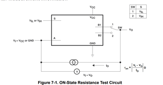
 

I would be grateful if you could provide me the test condition and how to proceed with the negative current.

  • A negative current indicates that the current flows out of the pin, i.e., the switch is connected to a load that sinks current.

    The tests with VI = 0 V have a load that sources current.

    As shown in figure 7.1, the load is a constant-current source/sink, and the voltage is measured. Alternatively, connect a variable voltage, measure the current, and adjust the voltage until the current matches the test condition.