This thread has been locked.
If you have a related question, please click the "Ask a related question" button in the top right corner. The newly created question will be automatically linked to this question.
Hello,
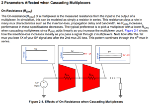
We currently have a preliminary design which uses multiple TMUX1108s to create a 2-stage cascaded MUX. Inputs to the first stage of the TMUX1108s are analog inputs ranging from 0V - 4.096V, inputs to the 2nd stage are the outputs from the 1st stage MUXs, and the output of the 2nd stage MUX goes to an ADC (AD9225). Vdd for every MUX is 5V and Vss is grounded. 1st stage MUX switching occurs at upwards of 3MHz, which is pretty fast I believe. I don't see data on switching frequency limits in the datasheet, so if those exist please provide them
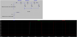
I can sweep & measure the 1st stage MUX inputs and confirm that they are being applied between 0V - 4.096V as expected, but when I measure the output of the 2nd stage MUX before the ADC it seems to saturate at about 0 - 3V maximum. I do not have the capability to measure data after the 1st stage MUX. So to be clear: I can apply an input to the first stage MUX that is 4V, but I only read 3V maximum prior to going into the ADC. From 0V to about 2.5V it is linear as I expect, but from 2.5V to maximum is compresses and saturates.
Could use some help. If there is a breadboard available I'd be interested in that as well
Thanks
-David
Hi David,
Thanks for reaching out here. Luckily, Rami on our apps team recently released an app note on cascading multiplexers!
Off the bat, the app note discusses how you see incremental loss when cascading so it seems like this is what you are dealing with. You also have doubling of on leakage in this situation as well.
In terms of a breadboard, this device doesn't have a dedicated EVM. Instead, it utilizes TI's generic Leadless Adapter.
Regards,
Alex
Thanks for the response. The TMUX1108 that we're using has a low Ron at ~4.5ohms, so I would not expect a loss as severe as the one we are seeing. I also ran a very basic circuit simulation in LTSpice modeling Ron and Con of two cascaded TMUX1108 with values from the datasheet. I similarly don't see significant loss.
Is there a way to calculate mathematically what the "X" loss per cascade should be for the TMUX1108?
Thanks,
-David
Hi David,
Unfortunately, no mathematical expression to calculate loss per cascade as there's multiple factors that go into the exact loss that occurs. I am not so sure that an LTSpice simulation would properly simulate cascading loss in this case. When cascading into a high impedance load, the app note shows a roughly 10% drop using a 2ohm Ron device. So this device would increase that loss slightly from that aspect alone. It's recommended to perform a bench level analysis of the cascaded networks compatibility with the specific system as use cases, system requirements and environments vary. Utilizing the leadless adapters should show that this loss is "natural" in this cascaded application.
Regards,
Alex