


Other Parts Discussed in Thread: SN74CBT3257C
Tool/software:
This is for a part that is being discontinued. We are currently using an Onsemi (74FST3257DTR2) and, datasheet wise, it looks like a good change to TI (TS5N412PW).
During testing we see that it doesn't act the same. To cleanly explain I will show some snips before I talk about them:
Close up:
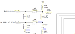
Close up 2:

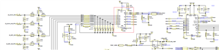
This is the test:
For this case I will focus on 1B1, 1B2 set up as inputs and 1A set up as outputs.
We set OE to ground to keep active, and a square wave to S to switch between the inputs.
We do this set up for two PCB boards. One with ONSemi and one with TI to be able to do side by side comparisons and testing.
1B1 input is a tringle wave.
1B2 floats (internal pull up as shown in the schematic)
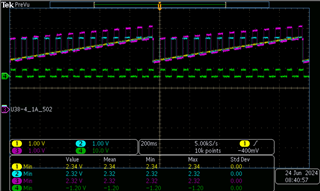
The green input is S
The yellow input is 1B1
The blue is the ONSemi output 1A PCB1
The ~purple is TI output 1A PCB2
Conclude they work different.
Question:
1B1 matches as expected
1B2 is floating (light pull up)
Expected that when s switched to 1B2 that it would be at the floating input and flat. The DC offset I would understand being a little off due to transistor choses between the two devices, but the slope looks like it is rising in the TI product. I do not understand that.
Could you explain the DC offset increase? I would like to hear an idea and/or another test to prove the reason for the difference. As I would like to test for that first in future endeavors. Also, if there is a simple resistor change on the pull up, that would be easy enough to do.
On a secondary note!
If there is also another drop-in replacement you would like me to add to my list of options I would also like that as well.

