Tool/software:
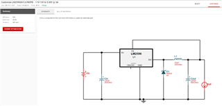
I used the power designer tool for the LM2596SX-5.0 buck converter(Vin min = 11V, Vin max = 13V, Vout = 5V, Iout max = 3A). The problem is I have a Cf capacitor in the bill of materials, but it is nowhere placed on the schematic. From what I have seen the LM2596S-ADJ sometimes requires a Cff CAP across R2, but in my case I have a fixed output LM2596 and I also have no R2 on the schematic. If it's not a mistake, than where should I place the Cf CAP?


