This thread has been locked.

If you have a related question, please click the "Ask a related question" button in the top right corner. The newly created question will be automatically linked to this question.

TS5A3359:制御信号(Digital Input)の電圧について

Part Number: TS5A3359

Tool/software:

1) VCC=3.3Vで使用する時

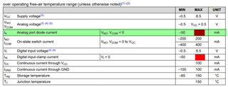
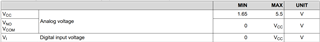
データーシートの4ページに、Recommended Operating ConditionsにVI=VCC(max)の記載が有ります。

データーシートの7ページに、Input Logic High VIH:2~5.5Vの記載が有ります。

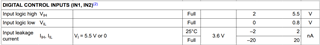
制御信号IN1/2はVCCより高い電圧を入力しても良いですか?

その時、制御信号(IN1/2)から電源(VCC)への電流の漏れ込みは無いですか?

2) VCC=5.0Vで使用する時制御信号IN1/2を3.3V系信号で駆動しようと考えてます。(Vin=3.0V~3.4V)

データーシートの5ページ記載の、Input Logic High VIH:2.4~5.5Vの規格は満足しています。
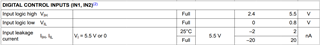
制御可能と考えていますが良いですか?

その時、電源(VCC)から制御信号(IN1/2)への電流の漏れ込みは無いですか?

上記1),2)共に異種電源系の接続となりますが、注意する事項はありますが?
どこかに電流制限用の抵抗が必要とか...

ご教授方、よろしくお願いします。

  • Hello,

    I believe that recommend operating conditions is a typo here. From the absolute maximum rating table it looks like there is only an ESD cell from the digital port to GND, but not one from the digital input to supply so there shouldn't be anything limiting you from going up to 5.5V on the IN1/2 pins.

    Note in red there isn't a positive rating. if there was an ESD cell there would be a positive rating. If there was an ESD cell you'd be limited to VCC, otherwise it's usually the max supply voltage. So in this, there shouldn't be leakage to supply.

    In the case 2 where VCC = 5V and IN1/2 is 3-3.4V that should be totally fine. Be aware though that you will likely see higher supply current than the typical value of the datasheet. When the control input is at GND or at least VCC then the supply current is at it's lowest.

    Thanks,
    Rami