This thread has been locked.

If you have a related question, please click the "Ask a related question" button in the top right corner. The newly created question will be automatically linked to this question.

TMUX1248: Pins don't have output can choose

Other Parts Discussed in Thread: TMUX1248, SN74AUC2G53

Tool/software:

Hi 

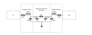
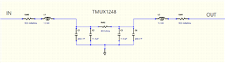
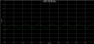
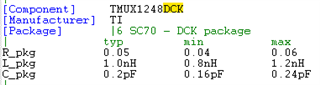
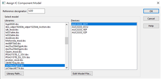
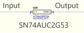
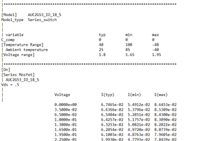
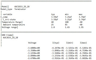
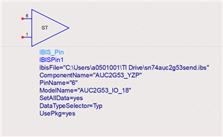
I have some problems about TMUX1248 IBIS model,

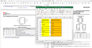
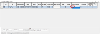
pin 1,3,4 should be I/O(input and output)
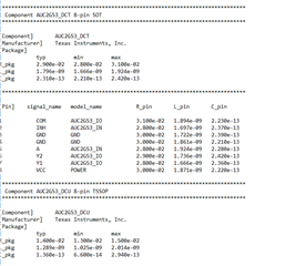
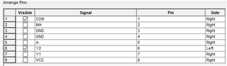
Pin Signal_name model_name
1 S2 nc
2 GND gnd
3 S1 nc
4 D nc
5 VDD power
6 SEL input

This IBIS model is for this website https://www.ti.com/product/TMUX1248?keyMatch=TMUX1248&tisearch=universal_search&usecase=GPN#params

Is there anyone who can solve this problem immediately

Thanks,

Kevin

  • The S/D pins are neither inputs nor outputs. An analog switch behaves similar to a resistor when the switch is closed.

    IBIS is capable of modelling such analog switches, but this has not been done for the TMUX1248. You would have to model the switch using discrete components, as described in the linked FAQ.

  • Hi Kevin,

    I agree with Clemens here and the FAQ he shared here should help you model this device using discrete components.

    Please let me know if any other assistance is needed.

    Regards,

    Kameron

  • Hi Kameron

    The software I use is HyperLynx VX2.14

    Can the solution in FAQ applicable to HyperLynx VX2.14 ?

    Thanks,

    Kevin

  • tmux1248.ibs
    Hi Clemens

    Can you help me to recreate IBIS model

    Because the simulation tool we use is HyperLinx 

    Thanks,

    Kevin

  • Hi Kevin,

    I am actually not familiar with hyperlynx as our team typically uses ADS for our simulations.

    However the FAQ linked in this post should be applicable to the hyperlynx environment.

    This is because you could use the package data for this device in combination with the ron and con information in the datasheet. to create a completely passive stand-in model for this device completely in hyperlynx. The Only Partial IBIS Model Available – No Through Path Data section of the FAQ should be the best help here.

    I am assuming you can use put discrete components together in hyperlynx.

    Please let me know if this helps and I am happy to continue to look into this with you .

    Regards,

    Kameron

  • 1715.tmux1248.ibs

    Hi Kameron

    Can you help me to recreate IBIS model?

    Because the risk of this solution is too high.

    We require using the IBIS model instead of building the circuit ourselves.

    Thanks,

    Kevin

  • Hello Kevin,

    Currently our team is working through a large backlog of ibis model request for customers and we will add this device to that list.

    While I cant give a timeline on when our design team and application team will be  able to work together to refresh the model for this the particular device, I would recommended using the passive component stand-in model as that can give accurate signal integrity simulations for your design.

    Regards,

    Kameron

  • Hi Kameron

    There are the datasheet, circuit and result

    Can you help me check that does the circuit and result is right?

    Thanks,

    Kevin

  • Hi Kevin,

    The design of this circuit looks correct.

    What is your input signal into this mux?

    Is the output signal the green waveform?

    As long as you signal is passing from input to output everything should be fine but please let me know.

    Regards,

    Kameron

  • Hi Kameron

    This screenshot is the result which I use the passive component stand-in model.

    The blue waveform is the input signal, and the green waveform is the output signal.

    This screenshot is the result which I use the IBIS model.

    The green waveform is the input signal.

    The Vdd is 1.8 V

    Please help me check the result is correct or wrong.

    If it's wrong, how to build the circuit.

    In addition, is there any IBIS model can replace TMUX1248 ?

    If you have it, could you provide it to me?

    Thanks,

    Kevin

  • Hi Kevin,

    The passive model you made does work and is passing a signal from input to output.

    The only problem I see is that there is some signal distortion between the blue input and green output signal of the mux.

    Because you are passing a triangle wave signal through the mux, the higher frequency components of the signal could be getting filtered out here.

    Can you confirm the fundamental frequency of your signal you are trying to pass hear?

    We can try to use a different mux like the SN74AUC2G53 ibis model, this is because it is a complete model and should provide better signal integrity with high frequency signals like you are passing.

    In addition is using a 1.8V supply a must?

    There are multiplexers with higher bandwidth than the sn74 device.

    Please let me know what you think about this and we can continue to figure this out.

    Regards,

    Kameron

  • Hi Kameron

    Hello, since these two TMUX1248 / SN74AUC2G53 are not pin-to-pin compatible, may I ask are mapping them as shown in the diagram?

    Thanks

  • Hi Kameron

    TMUX1248's package is DCK.

    SN74AUC2G53 has 3 type of packages PW, RGY, and RSV.

    Which package of SN74AUC2G53 I should use according to TMUX1248's package is DCK.

  • Hi Kevin 

    It's currently a US holiday. Kameron will respond back on Monday.

    Thanks

    Rami

  • Hi Kevin,

    Your mapping of the device pins are correct.

    In addition like you pointed out the SN74AUC2G53 is in 3 different packages and non of those are the DCK package.

    In addition the package names are in the file as well. I don't see RGV,PW or RSV in this file.

    DCT and DCU are leaded packages like the DCK

    Is evaluating a device without a DCK package a option?

    Is this the sn74auc2g53.ibsfile you are seeing online for the sn74 device?

    In addition ac parameter testing of devices of multiplexers(like the devices bandwidth) might be better in different simulators like pspice( passing a high frequency signal through a ibis model might give worse results than the actual performance of the device.)The pspice model should show more accurate to real life bandwidth perfomance.

    Would using pspice as a simulator be a option?

    Please let me know what you think and we can continue to look into this.

    Regards,

    Kameron

  • Hi Kameron

    So SN74AUC2G53 DCT and DCU can replace TMUX1248 DCK ?
    I think this screenshot is the right one

    As you say that passing a high frequency signal through a ibis model might give worse results than the actual performance of the device.)The pspice model should show more accurate to real life bandwidth performance.

    But I only can use HyperLynx as a simulator.

    Thanks,

    Kevin

  • Hi Kameron

    There are circuit and result.

    Input pin is 6, output pin is 1 is that correct? 

    The green waveform is the input signal.

    The red waveform is the output signal.

    The signal seems didn't pass SN74AUC2G53.

    Thanks,

    Kevin

  • Hi Kevin,

    Understood we can continue to use hyperlynx if that is all that is available and this kind of error when using Ibis models in Hyperlynx is common.

    I am not a expert in hyperlynx but from what I gathered hyperlynx can sometimes call the switch io paths only input pins.(This would not allow the model to pass signals)

    Because this is hyper lynx I would recommend  reading this e2e as it has steps to solve this problem.

    Please let me know if this helps and I can dig into it some more if needed.

    Regards,

    Kameron

  • Hi Kameron

    This e2e still can't solve the problem.

    Let me repeat my question.

    The signal can't pass SN74AUC2G53.

    The green waveform is the input signal, and the red waveform is the output signal.

    Normally, the model type should be "I/O" not "Terminator".

    And there should have output can select.

    Thanks,

    Kevin

  • Hi Kevin,

    The e2e post had some information about what I thought could be your problem in hyperlynx and how our teams models have sometimes had conflicts with this software in the past.

    However with the information you showed me I might be able to help more.

    From my understanding the series switch model type is the one we need to use to pass a signal through this model.

    This e2e post explains the difference between the series switch model type and the terminator model type.

    In the model selector field can you change to the series switch model type(AUC2G53_IO_18_S)?

    Does hyperlynx give you the option to do this?

    Please let me know the results of doing this and we can continue to see if this is the best option for you.

    Regards,

    Kameron

  • Hi Kameron


    In the model selector field I can't change to the series switch model type(AUC2G53_IO_18_S)

    Thanks,

    Kevin

  • Hi Kevin,

    Thanks for your response here and now I think we can get closer to a solution.

    I cant find a way to download hyperlynx on my computer, but we can try another trouble shooting idea here.( I am not familar with hyperlynx and this is what I think we should do next)

    Can you change the "IBIS Pin Model" field?

    Instead of saying  AUC2G53_IO maybe we can get it to say AUC2G53_IO_S

    If that works then you might be able to change the model selector field to AUC2G53_IO_18_S

    Finally after those fields are changed you might still see IO Buffer direction as INPUT which is not correct for multiplexers. Multiplexer inputs are not buffers and this post explains that. And with that information you should be able to use this switch in your simulations were you are passing a high frequency signal.

    In addition if this trouble shooting doesnt work we can make a passive standin for this device just like the TMUX1248 and see what  the results would be.

    Can you tell me the frequency of the signal you are trying to pass through the multiplexer here?

    Regards,

    Kameron

  • Hi Kameron

    I can't change the "IBIS Pin Model" field AUC2G53_IO to AUC2G53_IO_S

    It will be like:

    Is there method to change IBIS Pin Model" field AUC2G53_IO to AUC2G53_IO_S?

    And we don't want to use this solution "make a passive stand-in for this device", is there another solution?

    Thanks,

    Kevin

  • Hi Kevin,

    Thanks for sending this picture over.

    Taking another look at this ibis file it looks to be there is some missing information for every package except the YZP package of this device.

    The reason why the other packages like DCT wont model the series switch is because they are missing the pin mapping section.

    This section is important to model the series switch.( Only the yzp package of this device has this information and I was able to get this series switch set up in ADS)

    In my opinion the best thing to do here is use the AUC2G53_YZP  for your simulations.

    In the file i just sent you I took package data from the DCT and put that in the YZP section so you can get the best results for the DCT of the SN74 device

    This file should help you access the AUC2G53_IO_18_S information for the DCT  package.

    sn74auc2g53send.ibs

    Please let me know if this helps and we can continue to see if we can get the simulation setup for this device

    Regards,

    Kameron

  • Hi Kameron

    I had try change Series Pin Mapping from 2 to 1

    Although, the I/O buffer direction still input, but the signal had pass sn74.

    The yellow waveform is the input signal, and the blue waveform is the output signal.

    I want to ask that the way witch I change Series Pin Mapping from 2 to 1 is it allowed?

    And if it is allowed, is the result correct?
    If it is not allowed, is there any other way to solve this ?

    Thanks,

    Kevin

  • Hi Kevin,

    I actually think everything is fine here and now we have the correct simulation results.

    Changing the Series Pin Mapping from 2 to 1( function_table_group) doesn't not matter with this ibis file and this is allowed but actually you should not have to edit that at all.

    From my reading the function_table_group is numeric designator that helps tell the person reading the file know which series switch models are associated  to the same common control function( Logic High or Low on the select pin on this device)

    So for example when you pin 6 and pin1 are connected that alternately   means  COM<->Y2  are connected and the control logic is  (A=HIGH,INH=LOW).

    All of the different series model data in function table group 2 is available and you can pick any of the for models name there.

    We are using   AUC2G53_IO_18_S  in our scenario.

    In addition hyperlynx calls the io signal paths "inputs" and however that should not be a problem for us as you do have the series switch data selected(The Io buffer direction of Input is a incorrect naming in hyperlynx  and wont effect our series switch simulations)

    The results of your simulaitons are correct and please let me know if you need more assistance.

    Reagrds,

    Kameron