This thread has been locked.
If you have a related question, please click the "Ask a related question" button in the top right corner. The newly created question will be automatically linked to this question.
Tool/software:
Hi,
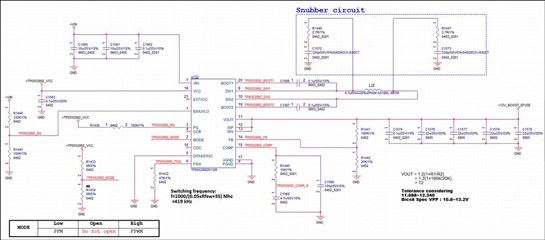
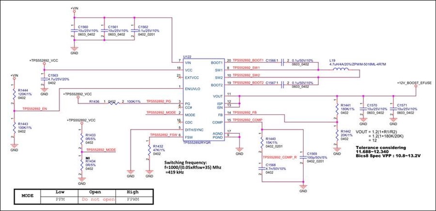
I have below schematic need review and few questions as below.
Thanks!
Jeff
Hi Jeff,
Thank you for reaching out. May I know what is the application here?
1. What is the input voltage range, output voltage and output current?
2.Can you provide part number of output caps for me to evaluate loop parameters?
3.Is there more caps in load side? If yes, please provide quantity and part number.
Regards,
Mulin
Hi Mulin,
Application is SSD.
1. Input voltage Vin=7V~14V (typical=12V) Vout =12V, Iout = 2A
2. 2 * 0603 or 0402 / 10uF / 25V /10% MLCC
3. Load side also 2 * 0603 or 0402 / 10uF / 25V /10% MLCC
Thanks!
Jeff
Hi Mulin,
Maybe can reference to below MLCC part number. thanks!
10u,0603,SMD,+-10%,25V,X5R,GRM188R61E106KA73D,MURATA
Hi Jeff,
Is this application eSSD ? May I know more information about customer and volume?
About the schematic, below is my feedback:
1.Recommend to add RC snubber in SW1 and SW2. 330pF+2.2ohm.
2.What is Isat of L19? Recommend to use Isat>8A because TPS552892 is 8A average current limit.
3.Add a 0.1uF 0402 cap in Vout pin and put it close to IC.
4.Only 3uF effective capacitance is left with 12V DC bias. Vout ripple will be huge and overshoot/undershoot will be huge. Recommend to add more caps. Please let me know if customer accept add more caps.
Regards,
Mulin
Hi Mulin,
1.Recommend to add RC snubber in SW1 and SW2. 330pF+2.2ohm.
2.What is Isat of L19? Recommend to use Isat>8A because TPS552892 is 8A average current limit.
3.Add a 0.1uF 0402 cap in Vout pin and put it close to IC.
4.Only 3uF effective capacitance is left with 12V DC bias. Vout ripple will be huge and overshoot/undershoot will be huge. Recommend to add more caps.
Schematic modify as below:
Is there any other suggestion to the schematic modification?
Hi Jeff,
Add 330pF/50V/0402 + 7ohm/0402 in SW1 and SW2 for snubber circuit. Do you think it is okay?
7ohm resistor will have little effect on the snubber. Customer can adjust it during test. 0402 package is too small. 1206 or 0805 is recommended.
Isat=4A. Iout_max is only about 2A~3A.
When Vin=7V, average inductor current will reach 12*3/0.95/7=5.4A. Considering some transient occasions, recommend to use 8A inductor since TPS552892 is 8A average current limit.
Is it enough to use 4*22uF/25V MLCC? (GRM21BR61E226ME44L,MURATA
only 15uF effective capacitance is left with 12V DC bias. Does customer have any transient overshoot/undershoot requirement? Can customer use caps with higher effective capacitance like GCM32EL8EF226KE08?
Regards,
Mulin