This thread has been locked.

If you have a related question, please click the "Ask a related question" button in the top right corner. The newly created question will be automatically linked to this question.

SN74CBTLV16211: IBIS

Part Number: SN74CBTLV16211

Tool/software:

Hi All,


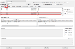
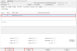
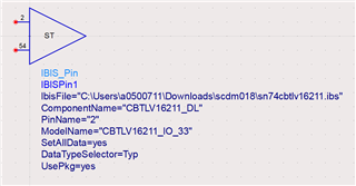
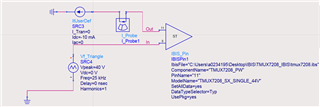
I have a question about IBIS.
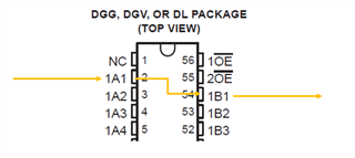
For example, is it possible to use IBIS to observe waveforms that include the effects of signals passing through the 1A1 and 1B1 pins?


Best Regards,
Ishiwata

  • Hello Ishiwata,

    Yes, you can simulate the IBIS model and observe the signals passing through the I/O pins.

    It can simulate signal integrity. 

    Thanks,

    Nir 

  • Hello Nir,

    Thank you for your reply.

    I understand that IBIS can only simulate the RCL of the pins.

    Are you saying that IBIS has information about the RCL inside the SN74CBTLV16211 and can therefore simulate the signal passing through the 1A1 and 1B1 pins?

    Best Regards,
    Ishiwata

  • Hello Ishiwata,

    If I am understanding your question correctly, in the IBIS model the I/O pins are modelled as passive series switches. 

    You can get the IV curve of those series switches using a simulation tool supporting IBIS.

    Thanks,

    Nir 

  • Hello Nir,


    Thank you for your reply.

    Since it is possible to measure, please tell me how to connect the circuit diagram for waveform analysis.

    The customer is using Keysight ADS.


    How can I connect the SN74CBTLV16211 1A1 (2 pins) and 1B1 (54 pins) IBIS models to observe the waveform including the effects of passing through the bus switch?


    Best Regards,
    Ishiwata

  • Hello Ishiwata,

    Today is a TI holiday. 
    please expect a reply by tomorrow EOD.

    Thanks,

    Nir

  • Hello Ishiwata,

    First download the IBIS model on TI.com. 

    Then in ADS you look for the IBIS_Pin component. Double click on the component to open this window:

    Select a component 

    Go to pin and click on pin 1A1

    Go to series model where you should see pins 2 and 54 are selected, then click and apply and ok 

    This will result in this model

    Now you have the model where the two pins are connected. You can use basic components to create a circuit and run simulations.

    Here is an example making a circuit to test Ron (this is for a different part, but the setup will be the same).

    For further information on ADS I recommend searching online for tutorials on how to use the software. 

    Thanks,

    Nir 

  • Hello Nir,

    Thank you for your reply.
    I will let my customer know how to do it.

    Best Regards,
    Ishiwata