This thread has been locked.

If you have a related question, please click the "Ask a related question" button in the top right corner. The newly created question will be automatically linked to this question.

TMUX6222: Termination setting for RS485/CAN bus

Part Number: TMUX6222
Other Parts Discussed in Thread: TCAN4552

Tool/software:

Hey , 

We recently using the TMUX6222 for the 120 Ohm termination enable/disable for CAN and RS485 communication.

the connection are as below 

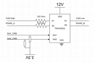
1. When the Sel1_CMD is High , we expect to have a disconnection between the S1 and D1 and then the termination is disable

2. When the Sel1_CMD is low , we expect to have a short between the S1 and D1 and then the termination is enable

In our case , its look that S1 and D1 are always shorted with no consideration of the state of Sel1_CMD ( We check that the TMUX6222 received the Sel1_CMD correctly (High=3.3V and Low=0V))

we checked it by measuring with the scope on the resistance 120 ohm pad that close to the TMUX622 (SEl1_CMD= high --> I should measure CAN_H only, SEL1_CMD=low i should measure CAN_L) but in my case i always measure the CAN_L

DO you have idea why its happening ?

  • Check the resistance between S1 and D1. (There might be a solder bridge.)

    The chip might be damaged. Try replacing it.

  • HI Clemens,

    We checked it in few board and we got the same behavior , Also note that its happening on both port (S1-D1 and S2-D2).

    We measured the resistance between S1 (CAN high)  and D1 (CAN LOW) and found 33Kohm (the board is not powered).

    After remove the IC , we still measured 33K ohm on board.

    This resistance become form the 2 CAN IC that we have on the bus TCAN1044 and TCAN4552 (Each of them have differential resistance between 50 to 100k) .

    Bottom line , its look that the device is not damage ...

    We also measured the current thought the IC , and find that the same current flow when the Sel1 is high or low with no difference (the channel is always short).

    We need your help to understand what wrong with our design

  • The schematic appears to be correct.

    What voltages do you measure at the SEL1/2 and VSS pins, relative to GND?