Tool/software:
Hi Teams
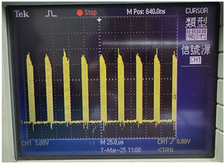
The current test found that the output frequency of the measured SW point is abnormal.
The design value is 500kHz,
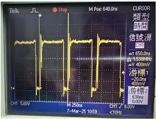
Let’s stretch the timeline to see the following:
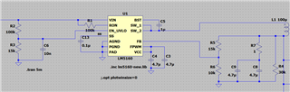
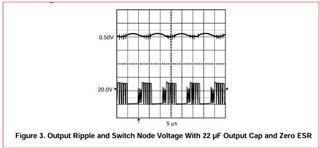
The subsequent speculation is that there is no ESR resistor above the output capacitor.
Because the waveform trend is close to the official website data,
But the situation is the same after reworking the circuit.
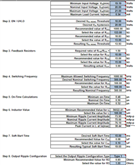
The following data analysis and calculation are used to discuss whether the design value is wrong.
Vin = 20V
Vout = 5V
fsw = 500kHz
Ron = Vout / (fsw * 1 * 10^-10) = 100k
Transformer inductance = 100uH
ΔIL = Vo * ( Vin – Vo ) / ( Vin * fsw * L ) = 0.075
Resr > 25m * Vo / ( Vref * ΔIL ) = 0.83
I used a 1 ohm resistor as the ESR resistor and the waveform was abnormal.
Could you please tell me which place is most likely to be abnormal?
Thanks.