This thread has been locked.

If you have a related question, please click the "Ask a related question" button in the top right corner. The newly created question will be automatically linked to this question.

TS5A23157-Q1: Can I use this part as a replacement part for G6K-2F-Y-DC5 Signal Relay.

Part Number: TS5A23157-Q1

Tool/software:

Hello team, 

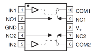
I have a product which uses G6K-2F-Y-DC5 Signal Relay from Omron Electronics to switch between two signals and it works as expected. While I was looking for automotive grade IC replacement for this relay I found that TS5A23157-Q1 (TS5A23157QDGSRQ1) fits my signal switching requirements perfectly.

Below is the internal connections diagram for the relay,

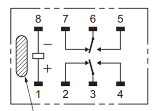
which is exactly same as TS5A23157-Q1 except the fact the it has two trigger pins which is fine for me. The signals am dealing with are 0.5 V to 4.5V DC analog signals which runs into engine ECU as sensor signals.

Now, the reason to create this question is that am thinking of directly going into small production batch by replacing the relay with your TS5A23157-Q1 without ordering one IC and manually testing it to see if it works. Am pretty confident that this IC must work well as relay replacement but am not a 100% confident and I just do not want my ordered PCBs to go waste so can someone or preferably an applications engineer let me know if am going down the right path. Please point out which parameters I might want to recheck.

Thanks in advance!

  • Hi Sid,

    We actually have an application note that may be helpful here:

    When to Replace a Relay With a Multiplexer

    If you know that your signals will be 0-5V and your I/O's will also be 0-5V one of the main things to check to make sure it's fine in your system is the RON flatness, from a performance persptective. With 5V the RON is still pretty flat though (4ohms) so it should work fine.
    The other big one would be the current. The TS5A23157-Q1 support up to 50mA on the I/O's whereas the relay support significantly higher. But if your system only calls for <50mA, the replacement should work. 

    Let me know though if you have any specific concerns though that I can help address too. 

    Thanks!
    Rami

  • Hey Rami,

    Thanks a lot for the quick reply! Am sure that my I/O and Signals are not crossing 5V at any point of time. I now have the following questions for you,

    1) Where can I find the Ron vs Vs graph for this particular device? Like shown in the app note figure 7-1. Is Ron for this device flat /same from 0 to 5V range?

    2) Am not sure about the current rating of my signals, I never measured it to be honest. How can I measure this using standard tools like multimeter? What I can think of is to measure the voltage across a shunt resistor and use V/R to measure current, is this enough? or do I need an oscilloscope to see peaks and stuff?

    Thanks,

    Sid

  • Hi Sid,


    The RON curve is on page 10 of the datasheet. Figure 6-1

    You'll be looking at that V+ = 4.5V case

    That method would be fine to measure the current. Whether you wanted to see peaks would really depend on how your system and your personal preference. It would be best practice though to see the peaks. If you know though the signal is pretty stable, it may not be necessary. I would at the least measure with an o-scope the voltage and see if the voltage spikes considerably anywhere. 

    Thanks,
    Rami

  • Hi Rami,

    Understood. I really appreciate your support.

    Thanks a lot!