TMUX4051-Q1: Design choices for two multiplexers sharing an output trace on the PCB

Part Number: TMUX4051-Q1
Other Parts Discussed in Thread: MUX36S08

Tool/software:

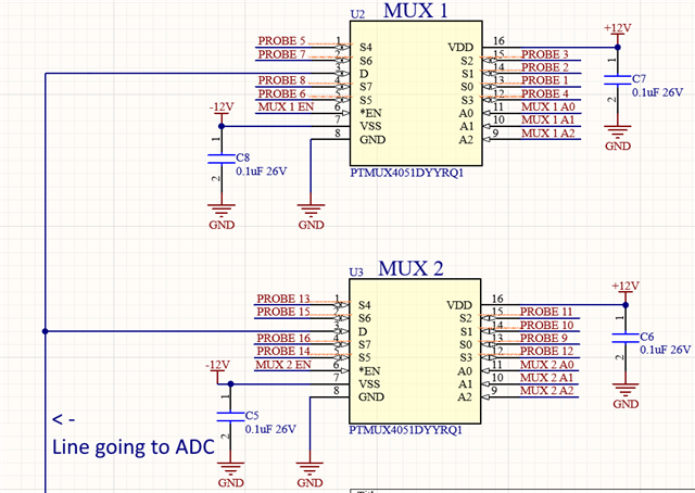
I wonder if having two multiplexers sharing the same output line is going to give me issues with signal clarity.

I also wonder if the PROBES which are the inputs of the multiplexers are okay with floating, they are literal probes and the user connects them at will, until he connects them thought they float.

If anyone can clearly see isues with this way of doing it, please let me know and if you can suggest an alternative way id be grateful for ever.

  • Hi Valerio,

    Tying your outputs together isn't an issue, just be aware that some specs will be increased. For example, if MUX1 is on and MUX2 is off then your capacitance on that shared channel will be CON + COFF. Another one would be leakage on that trace would be ION + IOFF as well. 
    It's pretty marginal differences though so it should be good, as long as you're not at your loading limits for that trace already.

    As for the floating traces, it should be fine. If you're in a high frequency and noisy environment, they may pick up noise and it could show up on the selected signal but in terms of functionality, it won't be an issue to leave the I/O's floating. 

    Thanks,
    Rami

  • Hi Rami and thank you for your fast reply,

    So my chances are good and i wont need an aditional MUX to switch between MUX1 and MUX2 outputs? Almost to good to believe not going to lie, i was worried about any kind of peculiar behaviour from the CMOS nature of the 405, even a couple of mV off would ruin my ADC measurement so i want to aproach this with the mindset of better safe than sorry.

    Cheers again.

  • Hi Valerio,

    No problem! Sorry couldn't back to you us fast this time but to answer your question, it would depend on the input impedance of the ADC, your source impedance and your test conditions. If we assume you'll work closer to room temperature, then you're probably fine. For example if we take the extra 0.3nA from the room temp off-leakage and say your ADC input impedance is 1Mohm, then you'll be looking at about 0.3mV error. As temp increases, this will be worse of course.

    If you're wanting to play it super safe, the MUX36S08 has single digit pA leakage specs that would help minimize the error even more. But if it needs to be automotive rated, then the TMUX4051-Q1 would be the best option.

    Thanks,
    Rami

  • Thanks for the input Rami, first time iv taken the short road to the solution and someone backs me up hehe. No need for 3rd MUX then.

  • No problem Valerio! Short and simple can work sometimes haha
    One last thing I forget to mention, just to help with the solution implementation - You'll just need to use the EN/ pins to make your logic work and you can tie your A0, A1, and A2 from MUX1 and MUX2 together to select through the 16 different inputs. 
    So instead of 8 logic pins like you have now it looks like, you can narrow it down to 5:

    MUX1EN MUX2EN Shared A2 Shared A1 Shared A0 Shorted D outputs connected to
    0 1 0 0 0 MUX1 S0
    0 1 0 0 1 MUX1 S1
    0 1 0 1 0 MUX1 S2
    0 1 0 1 1 MUX1 S3
    0 1 1 0 0 MUX1 S4
    0 1 1 0 1 MUX1 S5
    0 1 1 1 0 MUX1 S6
    0 1 1 1 1 MUX1 S7
    1 0 0 0 0 MUX2 S0
    1 0 0 0 1 MUX2 S1
    1 0 0 1 0 MUX2 S2
    1 0 0 1 1 MUX2 S3
    1 0 1 0 0 MUX2 S4
    1 0 1 0 1 MUX2 S5
    1 0 1 1 0 MUX2 S6
    1 0 1 1 1 MUX2 S7


    Hope that made sense!
    -Rami