This thread has been locked.

If you have a related question, please click the "Ask a related question" button in the top right corner. The newly created question will be automatically linked to this question.

TS5A3166-Q1: Switches & multiplexers forum

Part Number: TS5A3166-Q1


Tool/software:

To whom it may concern,

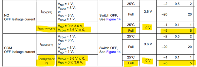
Sections 7.6 (3.3 V Supply), 7.7 (2.5 V Supply) and 7.8 (1.8 V Supply) in "SCDS357A –JULY 2014–REVISED DECEMBER 2014", have different figures for parameters "INO(PWROFF)" and "ICOM(PWROFF)", for what appears to be the same test conditions (i.e. VCOM = 3.6 V to 0 V, VNO = 0 to 3.6 V and V+ = 0 V, Full Temperature Ta = -40 C to + 85 C).  I've summarised these below:

Section, INO(PWROFF) [uA], ICOM(PWROFF) [uA]
7.6 (3.3 V), ±  5  uA, ±  5  uA
7.7 (2.5 V), ± 15 uA, ± 15 uA
7.8 (1.8 V), ± 10 uA, ± 10 uA

It is unclear to me why, when the test conditions are equal, are these figures different.  Is this correct?

Look forward to hearing from you.

Many Thanks,
Bhav

  • Hi Bhav,

    Could you please clarify which figures are different? From what I'm seeing for INO(PWROFF) and ICOM(PWROFF) in sections 7.6, 7.7, & 7.8, all refer to Figure 14.

    Best,
    Katy

  • Hi Katy,

    Thank you for your speedy response.

    By 'figures' I meant the leakage current numbers specified.  I've summarised from the datasheet as follows:

    Datasheet Section , INO(PWROFF) [uA], ICOM(PWROFF) [uA]
    7.6 (3.3 V)              , ±  5  uA                   , ±  5  uA
    7.7 (2.5 V)              , ± 15 uA                   , ± 15 uA
    7.8 (1.8 V)              , ± 10 uA                   , ± 10 uA

    Here are the excerpts these numbers have been summarised from:

    From Section 7.6:

    From Section 7.7:

    From Section 7.8:

    As you can see, the 3 sections have 3 different leakage currents specified, but the test conditions are all the same i.e....

    - Vcom = 0 to +3.6 V
    - VNO = 0 to +3.6 V
    - Tambient = -40 C to + 85 C
    - V+ = 0 V (unpowered)

    Please could you clarify, why the leakage numbers specified are different in the 3 sections, when the test conditions appear to be identical?  Is this correct?

    Look forward to hearing from you.

    Many Thanks,
    Bhav

  • Hi Bhav,

    Thanks for the clarification. Yes, I agree that something is off here. This part is over 10 years old, so I don't have an immediate answer on what is correct, but I have brought it up to the team and we are looking into it.

    Please let me know if you need any other help!

    Best,
    Katy

  • Thank you for following this up Katy.

    Any urgency you can put on this request would be hugely appreciated.

    Look forward to hearing from you.

    Many Thanks,

    Bhav

  • Hi Bhavesh,

    As we will have to allocate resources to re-take data, I cannot guarantee a quick resolution. However, please know that we are working on getting this resolved.

    If the difference between the specs is important to you, I would suggest either assuming the worst of the three option (+/-15uA) in your design, or taking the measurement in your setup.

    Best,
    Katy

  • Hi Katy,

    Will TI guarantee that COM / NO pins (from any given part i.e. process variation) will not leak more than +/- 15 uA when powered down and driven with 0 to +3.6 V over -40 C to +85 C ambient conditions?

    Look forward to hearing from you.

    Many Thanks,
    Bhav

  • Hi Bhav,

    Yes, that is our max datasheet spec for the INO/ICOM(PWROFF) spec.

    Best,
    Katy