This thread has been locked.

If you have a related question, please click the "Ask a related question" button in the top right corner. The newly created question will be automatically linked to this question.

Input/Output capacitance measurements for TS12A12511

Other Parts Discussed in Thread: TS12A12511

Hi Team,

I am looking to get an idea of how to properly measure input/output capacitance.

Here is a brief background of what I am trying to do:

I am evaluating various switches (mechanical relays, solid state relays, analog muxes, etc) for ATE boards.

Current specs of interest are on-resistance, input/output capacitance, and leakage current, but I am having a hard time to measure the capacitance of analog muxes. (not only TS12A12511 but other analog muxes as well)

I do not have any background of analog muxes, and thus I am not quite sure how they are designed as compared to other solid state relays.

I use two LDR meters: E4980A and 4263A

These two meters have 4 terminal measurements. (high force, high sense, low force, and low sense)

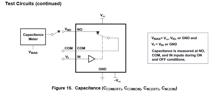
I tried to measure the capacitance using these meters between two nodes when the switch is off (not connected): NO-COM, NO-IN, NO-GND

However, I am not able to measure the expected capacitance in the datasheet.

Could you please describe how to measure the input/output capacitance when using the above LCR meter?

Thank you,

Jared

  • Jared,

    Could you draw a picture showing where you are placing the probes, "using these meters between two nodes when the switch is off (not connected): NO-COM, NO-IN, NO-GND."?

    To make the measurement you place the high force and high sense probes on the signal path you want to measure the capacitance and the low force and low sense probes to ground. 

    What readings are you getting for the capacitance?  I will check with our validation team to provide more information on how these measurements are taken.

    Thank you,

    Adam

  • Hi, Adam

    The question was original coming from me.

    I tried to measure as you mentioned - High sense and high force lines are connected at the pin of interest, and low sense and low force lines are connected to ground. It basically returns very unstable capacitance value, and the value keeps moving (0.01pF to 100pF)

    Then, I probed high force and high sense at COM pin and low force and low sense at NO pin when the switch is not connected to NO. (I wanted to see if I can measure any capacitance between two nodes). Same results. And, I tried all the combinations, but the results are the same.

    I see the datasheet has a test condition at f=1MHz, and our LCR meters have operating ranges of 100kHz and 300kHz. I don't think it is a limitation factor though.

    Could you please confirm that probing high force and high sense at the pin of interest and low force and low sense at GND is a correct way to measure your datasheet specs of NC, NO OFF capacitance and COM, NC, NO ON capacitance?

    Thanks in advance,

    Sehun

  • Sehun,

    The capacitance measurements we take for these switches are measured under the following conditions listed in the datasheet.

    The capacitance meter we use only has 2 probes we do not have a meter with force and sense probes. 

    How are you biasing the switch when you are making your measurements? 

    Ccom(off) does not mean that Vcc = 0V  but rather that the logic on the IN pin is selecting the other signal path. 

    Adam  

  • Thanks Adam for your response.

    Here, whether 4 probes or 2 probes does not matter since force and sense of 4 probes must be terminated at some point anyways. In my case, sense and force lines are terminated at close to the DUT pin.

    So, when you use 2 probes, it looks like you are measuring between the pin of interest and GND. Please kindly confirm. (GND to NO, GND to NC, GND to COM)

    The meters I am using have biasing option of up to 1.5V, and I gave 1V biasing. If higher biasing than 1.5V is needed, I would need to use additional power supply to give a bias.

    What bias voltage level are you recommending though?

    I am using this switch with 12V single supply.

    Thanks again.

  • Sehun,

    We use a Hewlett Packer 4191A RF Impedance analyzer to make the capacitance measurements.  Bassically what you are doing is injecting a known square wave into the device and measuring the distortion of the reflection.  You then can calculate the impedance of the path by comparing the difference of the two signals.  

    So, when you use 2 probes, it looks like you are measuring between the pin of interest and GND. Please kindly confirm. (GND to NO, GND to NC, GND to COM)

    Yes, when we make the measurement we are measuring GND to NO, GND to NC, GND to COM)

    What bias voltage level are you recommending though?

    The datasheet states Vbias = Vcc, Vio, or GND. The bias voltage just moves the operating point of the FET during the test.  Since our devices are designed to operate with a flat impedance response from 0V to Vcc,  this shouldn't have much of an effect on your impedance measurement.   

    Since impedance is a function of frequency, the frequency you take a capacitance measurement can effect your result.  We measure our capacitance at 1MHz since this is the lower limit of our equipment in the lab. 

    I am using this switch with 12V single supply.

    That is a valid supply voltage for this measurement. 

    Adam