I developed a board with a TS3L501E mux and am facing some failures of this IC. I've read your other blog community questions about biasing and placement of magnetics, but am still unsure what causes the failures. The failure is that some single ports are not working anymore and a lower off Isolation and a higher on resistance can be measured.
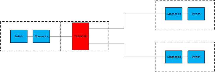
This is basically what the system looks like at the moment:
Some thoughts about it:
- The blue components are ethernet switches with magnetics
- the idea was to mux a switch port on the left to two other switches
- the components on the left share the same ground, the switches to the right are isolated
- From my understanding, additional magnetics are not required (as stated in this post: e2e.ti.com/.../1124710
- ESD protection has not been included due to internal ESD protection
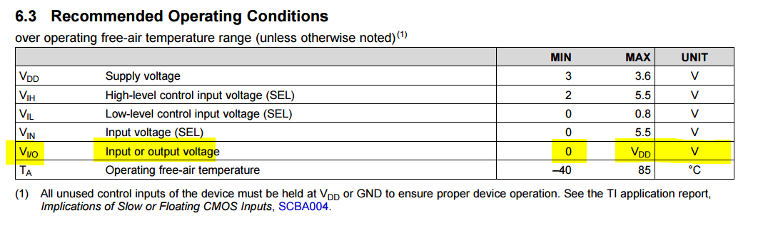
- The TS3L501E I/O connect directly to the ethernet lines from all magnetics
One cause for the failures can be that the lines might be driven if the mux is powered off. This is because the left block has to be restarted in some circumstances while the rest of the system is still running. Would it help to pull the signal lines low like suggested in this post: e2e.ti.com/.../1124710
Are the internal ESD diodes fully working, if the device is powered off? Can additional ESD diodes with series resistors to the TS3L501E reduce the chance of damaging the mux?
Or am I totally wrong and is it required to add magnetics after the TS3L501E to ensure properly biased signals. Do you have an idea on how to isolate the lines during restart case?
Thanks for any advice.
Regards,
Alexander