This thread has been locked.

If you have a related question, please click the "Ask a related question" button in the top right corner. The newly created question will be automatically linked to this question.

TS5A3159A: Asking for the TS5A3159 as audio signal switch distortion issue

Part Number: TS5A3159A
Other Parts Discussed in Thread: TS5A3159

Hi Team
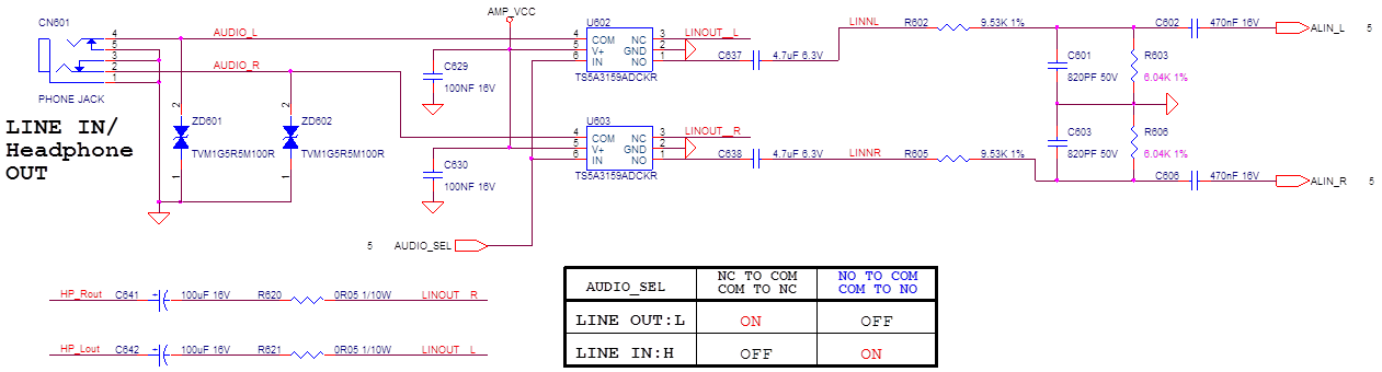
Cusotmer uses TS5A3159 as audio switch. Howeverm customer found the THD distortion is very bad.

Customer also bypass TAS5A3159, the signal THD is good.

Could you help review the schematic? Is TS5A3159 suit for the audio switch application?

here are customer schematic and the audio performance measurement data.

170725 APA2604C HP Out and SPK Out Test for G9217(V0).pdf

Thanks,
SHH

  • Hello SHH,

    We have a suspicion as to what could be causing these problems, but we would like to know a little more about your system.
    1) Could you confirm that you are using a 32 Ohm load for these tests?
    2) What is value that you have as the Vcc for the switch?

    Thank you,
    Louie
  • Hi Louie,
    1) Could you confirm that you are using a 32 Ohm load for these tests?
    Yes,32ohm/50mW(VS spec)

    2) What is value that you have as the Vcc for the switch?
    AMP_VCC is 5.0V


    Thanks,
    SHH
  • Hello SSH,

    Could you take a couple probe measurements for me to check on a different hypothesis:
    1) The VCC pin sees 5V?
    2) What resistance do you measure across the switch when looking at LINOUT_R (between pins NC and COM)

    Thank you,

    Louie
  • Hi Louie,

    Do you have any comment for this?

    1)      The VCC pin sees 5V? could you use scope to measure the 5V waveform?

    5.2V


    2) What resistance do you measure across the switch when looking at LINOUT_R (between pins NC and COM)? Could you use the meter to measure the resistance?

    5.7 ohm (When POHNE JACK connect 32 ohm dummy load)

    Thanks,

    SHH

  • Hello,

    The measured resistance you have with your given set up seems a bit high when enabled, especially at the given Vcc level that you have measured.
    This raises a few more questions for me:
    1) During this instance, the Enable pin should be tied to LOW, as you mentioned in your truth table, is this correct?
    2) Could you confirm that the I understand the flow from the Analog Precision instrument, that the input comes through the 32Ohm resistor load, then to the switch, through the passives following before going back to the Analog Precision instrument? If not could you correct the flow of the signal?
    3) What is the minimum and maximum value which the Analog Precision instrument injects into the circuit? The reason I ask is because is because I noticed that your input was 0.650 Vrms, which translates to about 0.919 Vp, which would exceed the absolute minimum our switch can handle. If this is the case, could you try retesting with a smaller input value, such as anything less than 0.35 Vrms?

    Thank you for answering these questions,
    Louie