This thread has been locked.

If you have a related question, please click the "Ask a related question" button in the top right corner. The newly created question will be automatically linked to this question.

CD74HC4067: Power up question.

Part Number: CD74HC4067

Hello,

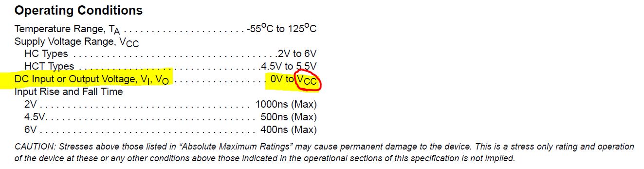
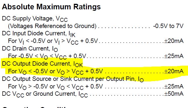
We are using a CD74HC4067 device on one of our designs. We have seen some strange operation when we operate on a fully loaded system. When we test the system on the bench all is well. We see the O/P of the mux switching around to all the 16 I/P channels. signals are relatively clean. Channel switch is pseudo random and switch period is 2mS. We have 16 input channels and the O/P channel tied to an ADC input of the uP. The enable pin of the 4067 is tied directly to gnd and I/P voltages may be present on some of these inputs before the device power supply is established. We are powering from 3.3V.

When we load up the system (extra loads on some PSUs - possibly slower PSU ramp times etc.) we get some peculiar operation on the O/P of the mux. It's like the switch impedance is greatly increased when it gets into this mode.

As the mux switches inputs we  see the O/P voltage level discharge very quickly (presumably during the switch break) and then ramping up in RC type profile with approx. 1mS time constant.

Our hunch at the moment is that it has something to do with power up conditions but it's difficult to debug as we don't have good access.

Main question is if there is any record of power up problems with this device (Vcc = 3.3V) especially if I/P voltages are present as Vcc ramps up and also the device enable is hardwired low.

Any help or debug ideas would be greatly appreciated.

Thanks and regards,

John Barrett.  

  • John,

    If there is a voltage on the signal path I/O pins > than Vcc  or it will violate the operating conditions in the datasheet.  We cannot guarantee the performance specs in the datasheet if the condition is violated. 

    Having voltages present on the signal path before Vcc is up typically causes the esd protection diodes to conduct and sink current through the signal path to the Vcc pin when the voltage is 0.5 V greater than Vcc.  This leakage current must be limited to 20mA or there is risk of damage or reliability of the device.

    Let me know if this leakage current is what you are seeing as peculiar behavior. 

    Thank you,

    Adam

  • Adam,
    Thanks for getting back so quickly. During normal operation the voltage on the signal path I/O pins is not > than Vcc. However not sure if this is the case during power up i.e. some of the I/P signals could be established before the 3.3V (Vcc) comes up. - it may be. Need to check.
    If this is the case then any leakage current cannot exceed 20mA as all the I/P channels are protected by input resistors.
    Also please note that this operation will not happen on every power up. Our impression is that all PSUs need to be fully discharged and then it's easier to reproduce. We can power up and down and get normal operation
    Can you imagine any scenario whereby the nature of the switch could change so that we get this type of performance. (Note that it still works in this mode but very poorly). My gut feeling here right now is that it is some kind of latch -up during power up.
    Have you heard of anything like this before ?
    We are going to isolate the O/P now and see if we still get the problem. We will load it with a small cap. At least then we can say that the effect has nothing to do with the uP.
    If needs be we can send some plots.
    Any other comments or ideas would be greatly appreciated.

    Thanks and regards,
    JB.
  • JB,

    I'm not quite clear on what your are observing as abnormal behavior so a scope plot might help. When we ask for scope plots we usually like to see the signal input, signal output, control logic line, and power supply.

    Another good debug technique that looks like you are already trying is isolating the devices. I usually recommend removing the switch and shorting the signal path to see if the issue still exists.

    I have heard of power up issues with signal switches where the voltage on the signal path is greater than vcc or below ground causing large amount of current to flow through the device causing damage but it might not be the case since you say you have the current limited.

    Adam