Because of the holidays, TI E2E™ design support forum responses will be delayed from Dec. 25 through Jan. 2. Thank you for your patience.

This thread has been locked.

If you have a related question, please click the "Ask a related question" button in the top right corner. The newly created question will be automatically linked to this question.

TS3A27518E: IBIS model description

Part Number: TS3A27518E

I need to analyze Signal Integrity between on QSPI interface. In the middle of nets we use analog multiplexers. I downloaded IBIS model   ts3a27518.ibs  from TI. 
I have a questions about sections [Series Pin Mapping] and about Model_type Series_switch that are in the IBIS file. 


Introduction

The component TS3A27518E-Q1 has 6 multiplexers. Lets look at multiplexer nr 1 only  - for simplify. 
The analog multiplexer has common node COM1 on first side and on two nodes NO1 and NC1 on the opposite side. 

In IBIS model in section [Pin] each pin has has model selector: 

[Pin]       signal_name  model_name           R_pin       L_pin       C_pin
|
1           COM1         TS3A27518B_COM       4.700e-02   1.028e-09   3.100e-13
8           NO1          TS3A27518B_NO        3.100e-02   6.770e-10   2.330e-13
23          NC1          TS3A27518B_NC        4.700e-02   1.015e-09   2.510e-13

All above selectors (TS3A27518B_COM, TS3A27518B_NO and TS3A27518B_NC)  refer to models that are assigned to correct power supply. I use 3.3 V. So for my design models are:
TS3A27518B_COM_33, TS3A27518B_NO_33 and TS3A27518B_NC_33. All of them are type of Terminator. They describe clamps but not the main behavior.

[Model] TS3A27518B_COM_33
Model_type Terminator


Description


The main behavior is described in [Series Pin Mapping] section:

[Series Pin Mapping] pin_2 model_name            function_table_group
|
8                    1     TS3A27518B_NO_33_S    1
10                   3     TS3A27518B_NO_33_S    1
12                   4     TS3A27518B_NO_33_S    1
1                    8     TS3A27518B_COM_33_S   1
3                    10    TS3A27518B_COM_33_S   1
4                    12    TS3A27518B_COM_33_S   1
...

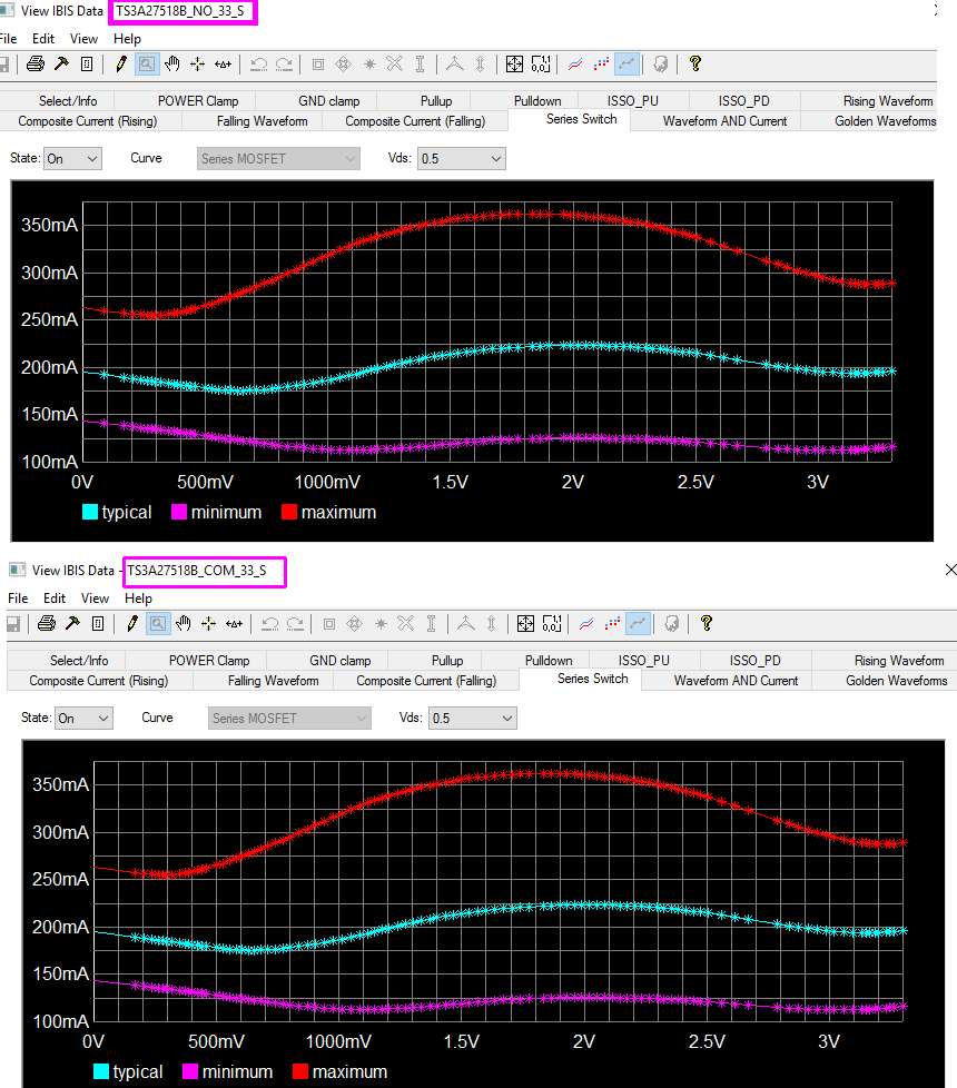
Between pins 8 and 1 is model TS3A27518B_NO_33_S and TS3A27518B_COM_33_S .

All above models are type of Series_switch:

[Model]       TS3A27518B_NO_33_S
Model_type    Series_switch

and they are very similar:


Questions: 


I understand that model TS3A27518B_NO_33_S  describes connection between pin N0 and pin COM, TS3A27518B_NC_33_S between pin NC and pin COM.
1°  What is purpose of model  TS3A27518B_COM_33_S ?
2° Why there are two parallel  models that operates exactly in the same way on the same pins?
3° Parallel models in [Series Pin Mapping Section] are not allowed in IBIS standard. The IBIS model "as it is" cannot be loaded into any program. Am I correct?
4° I suppose that user should delete/comment one model and use only second one as it is in section [Series Switch Groups]   - Am I correct?
5° Could I receive description to this IBIS file or configuration of this file that is ready to work?


Regards

Krzysztof Boron
Electrical Simulation Engineer

PS. List of Tags on this web is limited to A and B characters.


  • Hello Krzysztof,

    Thanks for your inquiry. We are looking into this. We'll get back to you in 1-2 days.

    Thanks,

    -Eric Kim 

  • Hi Krzysztolf,

    It seems the model was generated ~ 9 years ago by product line. Therefore it is very difficult to identify any additional supporting document (answer to your question #5).
    Having said that, the file passes the IBIS committee parser with no error. So we assume the model is compliant to IBIS specification.

    Based on my quick review on the model, the followings are my comment on your questions.

    #1) TS3A27518B_COM_33_S model seems to represent switch characteristic from pin 1 to 8 (signal direction). As it turns out, it is very close to that of TS3A27518B_NO_33_S. So user can use either model.
    #2)# 3)# 4) My recommendation is to comment out the signal path that is in parallel/duplicate. It seems you are using Hyperlynx for simulation. Unfortunately we no longer support Hypelynx. However, the following is a portion previous of response that describes how to set up a switch model in Hyperlynx. I also suggest you contact the HYperlynx for support.


    ***************************************************************************************************************************************************************************
    The following is a brief instruction on how to properly set up a switch model in Hyperlynx. Please give this a try and let us know how it goes:
    ***********************************************************************************************************************************
    1) You’ll need a driver and a receiver to connect the switch to.
    2) Place a MOSFET series, it’ll be on the left and looks like a CMOS.
    3) Select Models – Assign Models/Values by Reference Designator (.REF file)…
    4) In the Design’s parts list, select your component (e.g. U1), under Model/value, go to .IBS, and look around for your ibis file that has the switch model.
    5) Once selected, click on Assign Model, save your .REF file and close this window.
    6) You can then either double click on the box, or select and the go to Models – Assign Models/Values by Component.
    7) In this menu, choose a pin for connectivity. It should select the matching pin based on the model.
    8) Connect to your transmitter device and receiver and you can simulate.
    ****************************************************************************************************************************


    Thanks,
    -Eric