This thread has been locked.
If you have a related question, please click the "Ask a related question" button in the top right corner. The newly created question will be automatically linked to this question.
Dear, Sir.
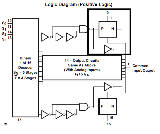
My customer is considering CD74HCT4067-Q1 as the Demux function.
They are asking the data latch(data holding) will be performed on each output,
i0 to i15.
I believe the schematic on the datasheet will be the latch circuit, but symbol
is not clear.
So, I would like to double-confirm this device has the data latch(data holding)
will be performed on each output.
Sorry to ask this kind of matter. Hoping to get your advice.
Best Regards,
H. Sakai
Dear, Sir.
Sorry my resending.
I had a big miss-understanding on my previous mail because CD74HCT4067-Q1
can work as an analog Demux. Please give your advice.
1. P/N block circled on previous mail is working as Switch? Correct?
2. Selected channel by S0 - S3 with /E, the Switch will be ON.
Other unselected channel Switches will be OFF. Correct?
Best Regards,
H. Sakai
Hideyuki,
The P/N in the diagram is supposed to represent a transmission gate switch (bilateral switch) which is a type of switch that has an NFET in parallel with a PFET. This switch architecture will support rail to rail operation and have a flat on-state resistance curve vs input voltage vs a single NFET switch which will clamp the input voltage at it approaches Vcc.
1) Yes, PN block is working as a switch
2) Correct, the S0-S3 are control logic pins that determine which switch path will be on while the others "off" paths will be high impedance.
Thank you,
Adam