


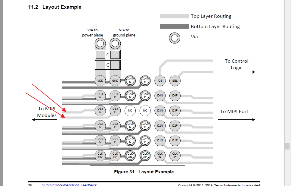
K. Shidara was trying to get the same answer that I am looking for 6 months ago. What is the recommended trace width and space recommended when attempting to fanout from the inner ball shown in the datasheet?
Original question:

K. Shidara was trying to get the same answer that I am looking for 6 months ago. What is the recommended trace width and space recommended when attempting to fanout from the inner ball shown in the datasheet?
