Other Parts Discussed in Thread: TMUX1204, TMUX1104, TMUX1119
Dear forum members,
I'd like to build a Sample and Hold (Hold and Track, precisely) circuit with TS5A3357 switch. Since PSpice model is provided, I imported it into my LTSpice and ran simulation.
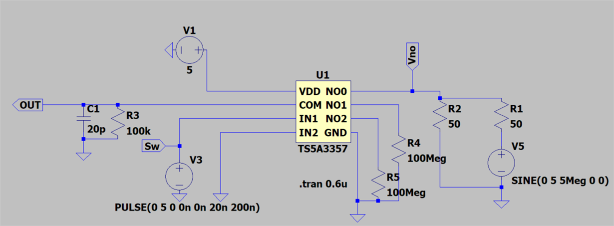
I followed the example circuit described in Figure 19. in TS5A3357's datasheet. Here's the circuit to simulate:
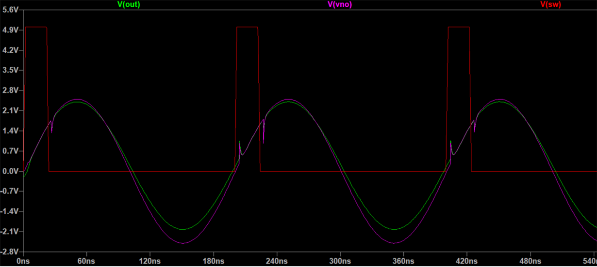
The SINE(0 5 5Meg 0 0) is the input of Sample Hold circuit. The signal "SW" decides whether to sample or hold. The signal "OUT" is output. The 20p capacitor is for sampling. However, the result of the simulation is different from what I expected. Here's the result:
If the switch is turned on, the V(OUT) follows the input as expected. But when the switch is turned off, much current seems to leak through the switch from input to output. Since the OFF isolation of TS5A3357 is -81 dB when Rl = 50Ohm, this leak seems much larger than that is expected from the datasheet.
Why do I see such a huge leak in this simulation?


