This thread has been locked.

If you have a related question, please click the "Ask a related question" button in the top right corner. The newly created question will be automatically linked to this question.

SN74LVC1G3157: Operation during VCC ramp up period

Part Number: SN74LVC1G3157


Hi Team,

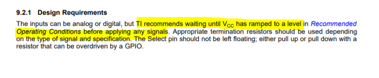
Recommended operating range of VCC is from 1.65V to 5.0V in the datasheet of SN74LVC1G1357, although the customer understood that, but they want to understand the operation of SN74LVC1G1357 during VCC ramp up period from 0V to 1.65V too.

Q1: During VCC ramp up period from 0V to 1.65V,
       What state is B1-pin, Hi-Z, Undefined state, or Output Low?
       What state is B2-pin, Hi-Z, Undefined state, or Output Low?

Q2: During VCC ramp up period from 0V to 1.65V,
       If VIH is applied to S-pin, is the "Table 1. Function Table" valid?
       Or, the "Table 1. Function Table" is not valid, and is it uncertain whether the terminal connected to A-pin will be B1-pin or B2-pin?

Q3: During VCC ramp up period from 0V to 1.65V, and if the "Table 1. Function Table" is not valid,
       Is there a possibility that B1-pin and B2-pin will be connected?

Thank you.

Best Regards,

Koshi Ninomiya

  • Outside the recommended operating conditions, correct operation is not guaranteed.

    There are two switches (transmission gates) between A and B1, and between A and B2. The A/B1/B2 pins are never driven high or low by the SN74LVC1G3157 itself. However, it is possible that any of the switches are closed (or partically closed), so that the voltages at the A/B1/B2 pins are visible at any of the other pins.

  • Hi Koshi,

    Please refer to the design recommendations for the SN74LVC1G3157:

    The recommended operating conditions are the parameters that we guarantee the part will operate as characterized through out the datasheet.

    You may also want to look at the new TMUX devices, TMUX1247 and TMUX1219  in similar configuration (2:1, 1 channel) with additional features like 1.8-V compatible control inputs and Fail-safe logic (Ensures the switch stays off and the logic pin does not back-power VCC when the voltage on the signal pin is greater than VCC) and lower RON (3Ohm typ).

    Regards,

    Saminah