This thread has been locked.

If you have a related question, please click the "Ask a related question" button in the top right corner. The newly created question will be automatically linked to this question.

TS3A5018: we have got TI failure report, it indicates EIPD on wedge pad, we need your help to explain which kind of conditions will lead to EIPD of wedge pad damages?

Part Number: TS3A5018

I have the same issue with Xiaojian, we have 2pcs fail TS3A5018, after TI Failure analysis, it indicates the EIPD on wedge pad, would you please help us to check :

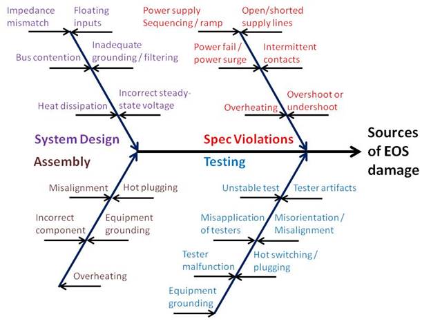
1) which kind of conditions will lead to an EIPD of wedge pad?

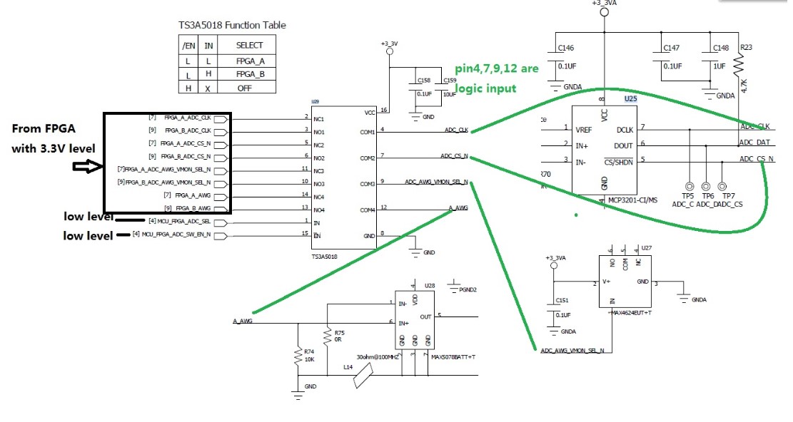
2) can you please help to check whether there is issue with our application?QEM-CCR-2002-00903 FA report.pdf

  • Hello,

    Thank you for your question. We are discussing your concern and I will get back to you shortly.

    Regards,
    Kate

  • Hello,

    Based on evidence obtained from failure analysis, Electrically Induced Physical Damage (EIPD) is the most likely cause of the issue. Based on the characteristics of this issue, a manufacturing non-conformance is judged to be unlikely. Therefore, it appears probable that the customer reported issue was caused by EIPD in the application environment, and TI recommends that the customer evaluate the application environment for sources of transient or steady-state Electrical Overstress. Detailed analysis and measurement of the customer’s board environment and the customer’s test environment will be required to identify the specific cause of EIPD.

    EIPD may occur during assembly or testing or may be a result of system design or specification violations, as shown below:

    While there is no apparent issue in your schematic, it is important to closely follow the below guidelines to prevent EIPD in your application.

    Application Parameters

    • Perform measurements of the application system, both under operating conditions and under testing conditions:
      • Confirm application complies with all Absolute Maximum Ratings and Recommended Operating Conditions in the datasheet (including voltage, current, timing, and temperature measurements);
      • Confirm power sequencing datasheet requirements are followed for each device in the application;
      • Confirm datasheet ramp rate requirements are followed for each device in the application;
      • Confirm that nodes on the board are operating at the intended voltage;
        • Specifically, confirm that pairs of nodes that are intended to be at the same potential are at the same potential;
      • Confirm power supply lines and signal lines are free of excessive noise;
      • Confirm power supply lines and signal lines are free of voltage spikes (positive or negative).

    Test Flow

    • Avoid hot switching:
      • Only connect / disconnect board-under-test when power is off;
      • Ensure bypass capacitors are fully discharged before disconnecting board-under-test;
      • Make sure relays and switches are connected / disconnected only when power is completely off;
      • Avoid hot switching between tests:
        • Do not change voltage values or current ranges while the power supply is connected or on;
        •  Do not turn off supplies between tests without allowing enough time for capacitors to discharge before starting the next test;
        • Do not use spring-loaded contacts that are at different heights, which could cause connection to any live supplies with undetermined sequences.
    • Include voltage / current clamps to safeguard against datasheet violations.
    • Manage test procedures:
      • Follow documented release process for test programs / procedures;
      • Audit test programs / procedures before release;
      • Maintain test programs / procedures under revision control.

    Best regards,
    Kate