This thread has been locked.

If you have a related question, please click the "Ask a related question" button in the top right corner. The newly created question will be automatically linked to this question.

TS5MP646: S parameter bandwidth

Part Number: TS5MP646

Hi, Team

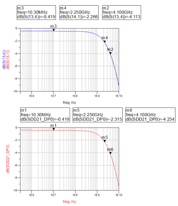
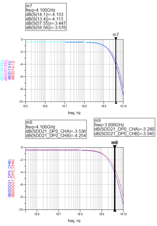
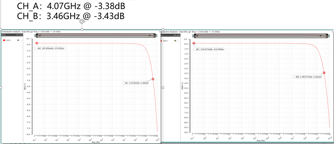
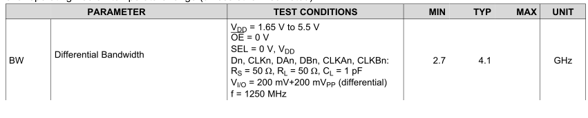
My customer used S parameter from ti.com to simulate and found the result BW is -4.254dB@4.1GHz, which is different from -3.32dB in datasheet curve. Is it correct result? As we mentioned, The datasheet plot shows differential bandwidth and the model is based on single-ended extracted measurement data. The expected differential device performance (which is most likely your use case) would be better than what the model would predict.

But he still has some confusion. 


  • Hi Daniel,

    Is you application using differential or single - ended signals?

    The datasheet shows Differential bandwidth plot - However, the s-parameter model is based on single-ended measurements.

    The capacitance in the single ended signal path is higher due to adjacent line capacitance to GND compared to the differential signal.

    Therefore for a given frequency the magnitude (in dB) would be smaller for differential vs single-ended expected differential device performance would be better than what the model (designed for single-ended) would predict.

    Regards

    Saminah.

  • Hi, Sir

    please help to explain the below questions

    1. your spec differential bandwidth is -3.32dB@4.1GHz. But I do simulation and result is -4.254dB@4.1GHz

    2. why are Channel A and Channel B  0.78db different at 4.1GHz

    3. below S parameter is download at your official website, the channel A S21 is better than channel B? 

       do you have any opinions? Can I argue that all switches are channel A better than channel B

    4.  if cphy symbol rate is 4.5Gsps, how to select switch ? 

     why you consider MUX Bandwidth >= 2*clock_frequency ? could you explain the reason in detail

  • Hi Dong Chen,

    Please see my comments below:

    1. your spec differential bandwidth is -3.32dB@4.1GHz. But I do simulation and result is -4.254dB@4.1GHz

    As I mentioned earlier, the model is created for single-ended signals whereas the datasheet plot shows differential bandwidth. See my comments below why differential device performance would be better than what the model (designed for single-ended) would predict.

    2. why are Channel A and Channel B  0.78db different at 4.1GHz, 3. below S parameter is download at your official website, the channel A S21 is better than channel B?    do you have any opinions? Can I argue that all switches are channel A better than channel B

    Yes, this is expected. Channel A should be higher BW than Channel B. See details below:

    The bench measurement were de-embedded so the bandwidth numbers are not including PCB parasitic.However actual system needs to consider those routing parasitic.Ch. B routing on PCB is shorter than Ch.A. If your PCB takes into account these parasitics, there can smaller difference between ch. A and ch. B.

    4.  if cphy symbol rate is 4.5Gsps, how to select switch ?  why you consider MUX Bandwidth >= 2*clock_frequency ? could you explain the reason in detail

    We typically recommend the signal switch per channel bandwidth to be ~1.5 times the “per channel data rate”. This is to make sure you are selecting switches with more bandwidth than what is theoretically required for a particular data rate to account for system losses that occur on PCB traces etc.  The rough formula we use to select switches is Bandwidth = (3/2)xDataRate which will provide sufficient margin. 

     The relationship between frequency and data rate is as shown below:

    You should consider the factor “3” is a rule of thumb. It will depend on the physical medium, capability of the driver and receiver you are using in your application, signal reflects, insertion losses etc.

    Regards

    Saminah


  • 1. your spec differential bandwidth is -3.32dB@4.1GHz. But I do simulation and result is -4.254dB@4.1GHz

    As I mentioned earlier, the model is created for single-ended signals whereas the datasheet plot shows differential bandwidth. See my comments below why differential device performance would be better than what the model (designed for single-ended) would predict.

    【Sven】could you comfirm whether you agree with the simulation result of SDD21=-4.254db@4.1GHz

    2. why are Channel A and Channel B  0.78db different at 4.1GHz, 3. below S parameter is download at your official website, the channel A S21 is better than channel B?    do you have any opinions? Can I argue that all switches are channel A better than channel B

    Yes, this is expected. Channel A should be higher BW than Channel B. See details below:

    The bench measurement were de-embedded so the bandwidth numbers are not including PCB parasitic.However actual system needs to consider those routing parasitic.Ch. B routing on PCB is shorter than Ch.A. If your PCB takes into account these parasitics, there can smaller difference between ch. A and ch. B.


    4.  if cphy symbol rate is 4.5Gsps, how to select switch ?  why you consider MUX Bandwidth >= 2*clock_frequency ? could you explain the reason in detail

    We typically recommend the signal switch per channel bandwidth to be ~1.5 times the “per channel data rate”. This is to make sure you are selecting switches with more bandwidth than what is theoretically required for a particular data rate to account for system losses that occur on PCB traces etc.  The rough formula we use to select switches is Bandwidth = (3/2)xDataRate which will provide sufficient margin. 

     The relationship between frequency and data rate is as shown below:

    [Sven]According to what you said, if we need to select a mipi switch for CPHY 

    data rate =2.5Gsps ;switch bw = 1.5 x data rate = 3.75GHz 

    but TS5MP646  spec describe min is 2.7Ghz and typ is 4.1Ghz. could I use TS5MP646 for CPHY 2.5Gsps ?

    data rate =3.5Gsps ;switch bw = 1.5 x data rate = 5.25GHz 

    TS5MP646  is not  satisfy 3.5Gsps, right ?

  • Hi Sven,

    The single ended s-parameter models were generated from simulations. Comparing them to silicon results can show deviations between the two. And as I mentioned earlier, the model is for Single ended mode so we are not comparing apples to apples.

    You can try to convert the single ended s-parameter file to a differential one and then measure. https://www.microwaves101.com/encyclopedias/mixed-mode-s-parameters

    The following details should help answer your questions related to high bandwidth support for the TS5MP646. 

    The TS5MP646 can support high bandwidth (2.5Gbps and 3.5Gbps)

    The bandwidth curve in the datasheet may not give you a clear idea but see below the eye diagrams that you can use to support the claim:

     The eye-diagrams show comparison of the signal without the switch and the signal going through the switch.   You can compare the signal integrity of the through path with the path including the TS5MP646 to show that the device has little impact on the signal.

    • 4.5 Gbps with TS5MP646 at 0.5Vpp

    • 4.5 Gbps through path (no switch) at 0.5Vpp

    We plan to include these in the datasheet soon.

    Regards

    Saminah