This thread has been locked.

If you have a related question, please click the "Ask a related question" button in the top right corner. The newly created question will be automatically linked to this question.

CD4051B: CD4051BNS: is there a pin-compatible alternative available?

Part Number: CD4051B
Other Parts Discussed in Thread: TMUX1308

We're having problems with CD4051BNS in an old MFG test fixture design.

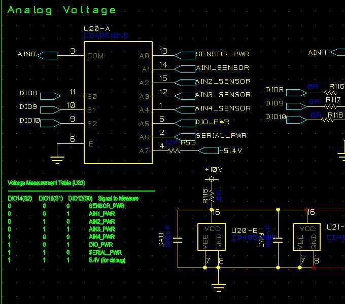
A0 operates at 0VDC to 6VDC

A1 - A5 operate at 0VDC to 3.3VDC

A6 operates only at 0VDC (not used)

A7 operates only at 5.4VDC

COM is high Z (NI PXI-6025e analog input)

S0, S1, S2 are controlled by DIO lines of the same PXI-6025e

We often encounter permanently open conditions, typically on channels A0 - A5 after a couple hundred test runs. These test runs are unattended, so likely not an ESD issue. After much debug effort, we've not been able to determine root cause. Do you see any issue with the design? Is there a pin-compatible alternative that we could try?

  • Hi John,

    We have pin to pin compatible parts, but I don't think they will meet your voltage needs. I want to help you troubleshoot this to find the root of the problem because that is not an expected result from recommended use. 

    So what is the voltage levels on S0, S1, S2? Specifically what does a "low" voltage look like and what does a "high" voltage look like on the line. This could cause issues.

    Also what voltage are you supplying to the part?  (VDD/VSS) 

    Best,

    Parker Dodson

  • Thanks for the reply.

    Voltage levels on S0, S1, S2 are low = 0VDC, high = +5VDC

    VDD is at +10VDC

    VSS is at 0VDC

  • Hi John,

    So the problem most likely lies with the select line voltage. From the datasheet:

    The issue is that at VDD = 10V, VSS = 0V, the input voltage required to turn on the switch is 7 Volts. Not 5, I am unsure why the parts were opening up at the 5 volts. So to solve the solution you need a 7V minimum signal to switch on the part.


    That being said, the alternative we have is the TMUX1308, but it is recommended for VDD of 5.5V, with an absolute maximum rating of 6 volts for VCC. The only port I am worried about on your device is the A0 line since it is at 6V. It might work with the 6 Volt VDD, but current limiting resistors would need to be on any signal that goes above 5.5V to ensure that current limitations are being followed. If this is a possibility let me know, but I understand if other system parameters can't be changed.

    Please let me know how else I can support you.

    Best,

    Parker Dodson

  • This make sense.

    The 6V on A0 is actually 24V that's being knocked down by a voltage divider to protect the mux and compensated in software, so it would be trivial to knock it down some more, but I don't know if I can get VDD off the 10V rail without a board spin. I'll look into it and maybe end up going with the TMUX.

    Thanks for the help!