This thread has been locked.

If you have a related question, please click the "Ask a related question" button in the top right corner. The newly created question will be automatically linked to this question.

TS5A23159: Can be used to segment RS485 stubs?

Part Number: TS5A23159
Other Parts Discussed in Thread: ISO15

Hi, for a project i'm planning to use the TS5A23159 in order to enable/disable RS485 devices lines, because i have many contact sensors that are placed around production environment, they monitor the door open/close status and using RS485 trancievers the slaves (that are equipped with an ATMEGA328P) will expose those information to the master of the bus.

Now, i want to be free to position those devices in my customer environment without worrying to set a slave address hardcoded in my firmware or using hardware dip-switches: the address will be dynamically managed from the MCU.

They are connected using a CAT5e cable and the total length is around 20/40 meters, the cable will transport: A-B-VCC-GND.

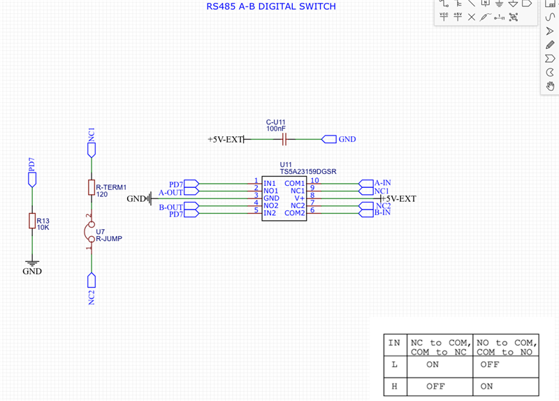
Every device is wired in daisy chain mode and the preceding device will control the RS485 data lines enable of the following device, using a TS5A23159 by the MCU (as reported in the image below) i want to implement this sort of "RS485 Digital Switch":

This approach will work? of will cause RS485 issues? keep in mind that the baudrate used is pretty low: around 38400, and that the trancievers on the slaves are all TI ISO15.

  • Just to clarify, you're just wanting to use this as a switch to effectively connect/disconnect the RS485 signals? Max voltage of 5V and Frequency (baudrate) of 38.4kHz. With the TS5A23159 this should be feasible. This switch has a low On-Resistance and On-Capacitance so it should maintain the integrity of the signal that passes through. It also offers powered off protection so when the device is turned off the signals can still be applied at the I/O pins up to 5.5V and not see damage. 

    My concern, and perhaps this comes from a misunderstanding, comes more in your setup. It looks like NC1 and NC2 can be shorted together with a jumper. Any reason for this? There are cases in which this will leave your signal floating, which we typically would recommend terminating to GND if unused. If these are the swtiches that are designated as your 'OFF' state, it honestly wouldn't make much of a difference what you do with them since your frequency isn't too high but here youre running your A-IN to your B-IN line when IN is low. Maybe that's what your intent is in which case this is fine. Additionally you have the INx pins pulled to GND. I'm assuming you'll eventually have these to a MCU of sorts to have controllability of switching them on/off, correct?  

    Thanks,
    Rami

  • I haven't heard from you in a while so i'm going to close this thread out but feel free to respond and reopen it with more questions!

    Rami

  • Hi Rami, thanks for the response and sorry for my delay.

    You're right, the IN1 and IN2 are normally pulled low and they will be wired to a MCU GPIO pins (in this case an ATMEGA328P) and controlled digitally: the main purpouse of that is that the MCU will enable those pins and "switch on" the RS485 bus A-B cables only when a specific logic condition will be reached.

    Regarding the NC1 and NC2 pins, when the switch is in OFF state, i've planned to short them to a 120 ohm resistor (when the jumper is closed) as required from modbus specifications for the latest node in the network.

    Do you think that these toughts will point me to the right direction?

    Thanks

  • You're definitely in the right direction. If i'm understanding correctly, the signals passing through are just the digital signals so we're not looking at any negative swings. If so, and the max voltage of the digital signals is below 5V, then you should be fine here!

    Rami

  • Thanks Rami,

    I confirm that the signals involved are RS485 signals, no negative swings but differential (as per definition of RS485 signaling).

    About voltage levels i'm a little bit confused...the RS485 by definition implements differential signaling that span from  -7V to 12V (as tolerated from ISO15 trancievers)...so it will be fine?

  • Yes the range of voltages for RS485 is from -7V to +12V but this doesn't mean that you're limited to the max of this range. Are you working with this max range, if so the TS5A23159 would not work here.  

    What are the actual voltages on A and B going through the multiplexer?
    If you're concerned with the level, i've seen the use of the CD405xB family which would have a higher voltage tolerance. Something like the CD4053B could be of some use?


    Rami

  • I haven't heard from you in a while so i'm going to close this thread out but feel free to respond and reopen it with more questions

    Rami