This thread has been locked.

If you have a related question, please click the "Ask a related question" button in the top right corner. The newly created question will be automatically linked to this question.

TMUX1204: Overheating chip right after board assembly, unable to reproduce later

Part Number: TMUX1204

Hello everyone

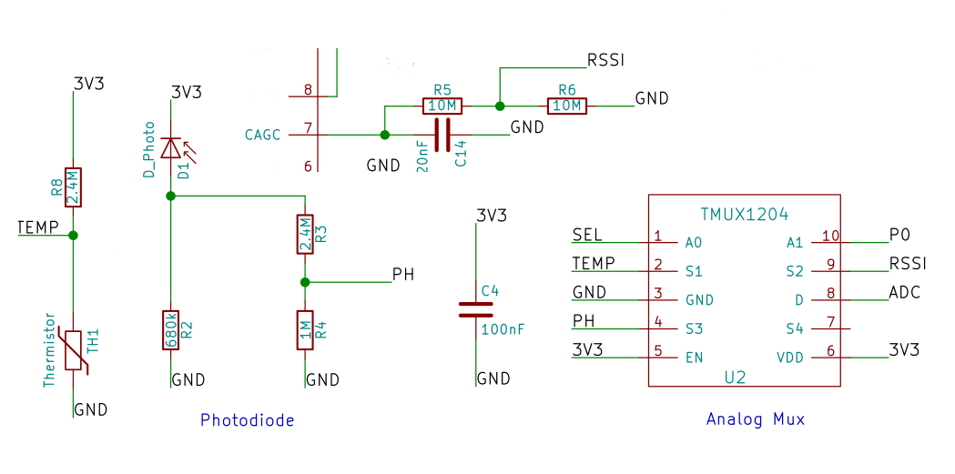
I am using a TMUX1204 to multiplex 3 analog signals to an unique ADC input, signals are between 0 and 1V to comply with the ADC max voltage. You can see the schematic related to the mux attached to this message.

A1 has a 10K pulldown that is not represented in the schematic, A0 is tied to a MCU GPIO that might be floating at bootup. S4 is left floating.

On a batch of 50 boards, 5 had overheating TMUX1204 chips when they were plugged. The problem either disappeared over time or when flashing MCU.

I am now unable to reproduce the issue and thus afraid to commit to a larger batch of boards without knowing what is going on. We tried to float A0 and A1 to reproduce it without luck.

Do you have any lead on what could be the issue and how to fix/reproduce it ? I'm considering tiying S4 to GND and adding a pull down to A0 but i'm a bit lost.

  • Hello,

    So my first intuition is that you need to pull down the A0 line to ensure a known logic state is there at all times.When it is floating, both FETs on the inverter connected to A0 could have both FETs partially conducting creating a larger current to go through the supply overheating the chip.

    But I do have a few more questions to help narrow down the answer.

    When you say the chip was overheating, do you mean the chip sustains damage due to a temperature to excess of 125C? If that is what you mean, where do you see damage on the chip?

    What is the ambient temp of the system and is there anything that gives off excess heat near the chip?

    Please let me know so I can see how we can narrow down this problem!

    Best,

    Parker Dodson

  • Hello

    Chip didn't sustain damage but was very hot despite the fact that in theory the current going through it should be very low. I can measure PCB temperature to tell you what is the ambient temp of the system.

    This chip isn't near a hot source, PCB is heated by a LDO and WiFi chip but nothing crazy, the TMUX1204 was getting much hotter than these two chips.

  • Hi,

    Yes when you can provide the temp of the board that would be good as it gives the reference point for the chip.

    But with all of that being said, the only really issue that would cause the part to heat up is current being pushed through it. If a select pin is floating it could create a pathway directly from VDD to ground - it may not be violating absolute maximum ratings on current from VCC to GND and cause damage, but this is the most likely culprit I'd imagine unless there are is some other source of current going through the switch, which based on the schematic I don't see any other place where a lot of current would happen right at startup before you reflash the MCU. Another reason I suspect its the floating voltage causing a conductive pathway from VDD to GND, is that it isn't happening on every unit, and that would account for variations in the pin voltage as it is floating and why you are having trouble recreating the issue. 

    Am I correct to assume that this is a low current application? 

    I think the best bet for solving the issue however is to add a pull-down resistor to A0 because this is the most likely cause of the issue. You can keep S4 floating because that is very unlikely to be the source of the heating, if using at higher frequencies it is advised to connect it to GND through a 50 Ohm resistor because it can slow down switching speeds otherwise.

    If you want to test the chip itself to try to recreate the problem, I'd connect A1 to a pull down resistor like in the schematic, and then sweep control voltages across A0 from 0V to VDD, in 50mV - 100mV steps primarily focused in the "Don't Know" Region of the logic. This is where you will see the highest currents between VDD and GND without expecting damage. 

    Please let me know if the ambient temperature and if you can perform the suggested test (if you can data along with the test would be helpful). 

    Best,

    Parker Dodson

  • Hello Parker

    Thank you for the in depth analysis, this is indeed a low current application even if it's not running out of a battery. We tried to sweep the voltage on A0 while monitoring current and chip temperature without being able

    to detect a spike in consumption or witness the overheating behavior we saw before.

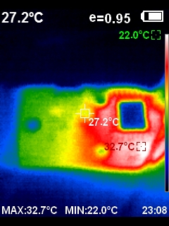
    We also did some temperature measurements with a thermal cam, it turns out that the PCB is heated to around 27 degrees celsius by a LDO but the mux is colder than the PCB thus is not self heating I assume.

    TMUX is located at the 27.2C marker, blue square is a wifi chip shielding, the hot point is the LDO.

  • Hi,

    That would  make sense that the LDO is causing a large amount of the heat on the board. LDO's are typically very inefficient and that inefficiency is due to the power consumed over the LDO, which is essentially just a pass FET that is controlled via a error amplifier. The heat measured here gives the ambient temperature - but it seems to be basically room temp, and unless the expected environment is going to be much hotter than ~25C these temperature results aren't concerning with what is shown because it is just a couple degrees uptick from 25C. 

    I know that you probably don't have exact data for the TMUX heating during the initial test, but do you think the temperatures seen in the picture you provided are similar to the max temperatures experienced by the IC itself?

    Also when sweeping voltages across how long was each voltage step, and what was the step size of your voltages? In general when we test supply current based on  voltage level, we sweep over the values as if we were switching a GPIO - it doesn't necessarily account for a use case where a voltage on the pin may be in an undefined logic state, as we typically advise against this usage of the part, and this duration could possibly see a larger current through the IC causing it to heat up.  I think the duration of the pulses should try to mimic the length between when the boards were powered up to when the Multiplexers started heating up and focus the area of interest to 50mV steps between  0.8V to 1.35V as this is the undefined zone for 3.3V. This shouldn't damage the part, but hopefully will re-create the issue so that you have confirmation of this. I think this is the most likely cause because current through the device is most likely causing the issue, and the most likely place current is being pulled from is a pathway from VDD to GND, and the switches themselves that could be active would have a higher Ron, and most likely wouldn't have enough current to significantly heat up the device. 


    Finally what was the soak time of the board before you took the temperature snapshots?

    Please let me know so that we can hopefully get to the bottom of this, I understand transient issues like this can be very hard to isolate.

    Best,

    Parker Dodson