This thread has been locked.

If you have a related question, please click the "Ask a related question" button in the top right corner. The newly created question will be automatically linked to this question.

SN74LVC2G53: MUX doesn't give any output

Part Number: SN74LVC2G53
Other Parts Discussed in Thread: SN74LVC1G98

Hello 

I'm using a MUX to implement a certain digital logic which has states A, B, and C. The truth table is as follows:

Inh: enable disable MUX

A: Switch

Com: in my case, input, always HIGH. Connected to a 5V voltage regulator. Same thing powers the MUX.

Y: Y1 and Y2 define my states.

Com Inh  A Y1 Y2 State
5V 5V X 0V 0V A
5V 0V 0V 5V 0V B
5V 0V 5V 0V 5V C

I tried this on a different through-hole MUX CD4053BE. It worked just fine. So I decided to integrate this circuit onto my PCB board. So I brought the surface mount version SN74LVC2G53DCUR.

For some reason, it doesn't work. Y1 and Y2 always read 0.8V. The truth table is as follows: 

Com Inh  A Y1 Y2 State
5V 5V X 0.6V 0.6V confused
5V 0V 0V 0.8V 0.8V confused
5V 0V 5V 0.8V 0.8V confused

Debug:

I measured the voltages at different pins. Its as follows:

A: 0 or 5V

INH: 0 or 5V

COM: 5V

Vcc: 5V

Y1&Y2: 0.6V and 0.8V

Please Help!

Varun R

  • Hi Varun,

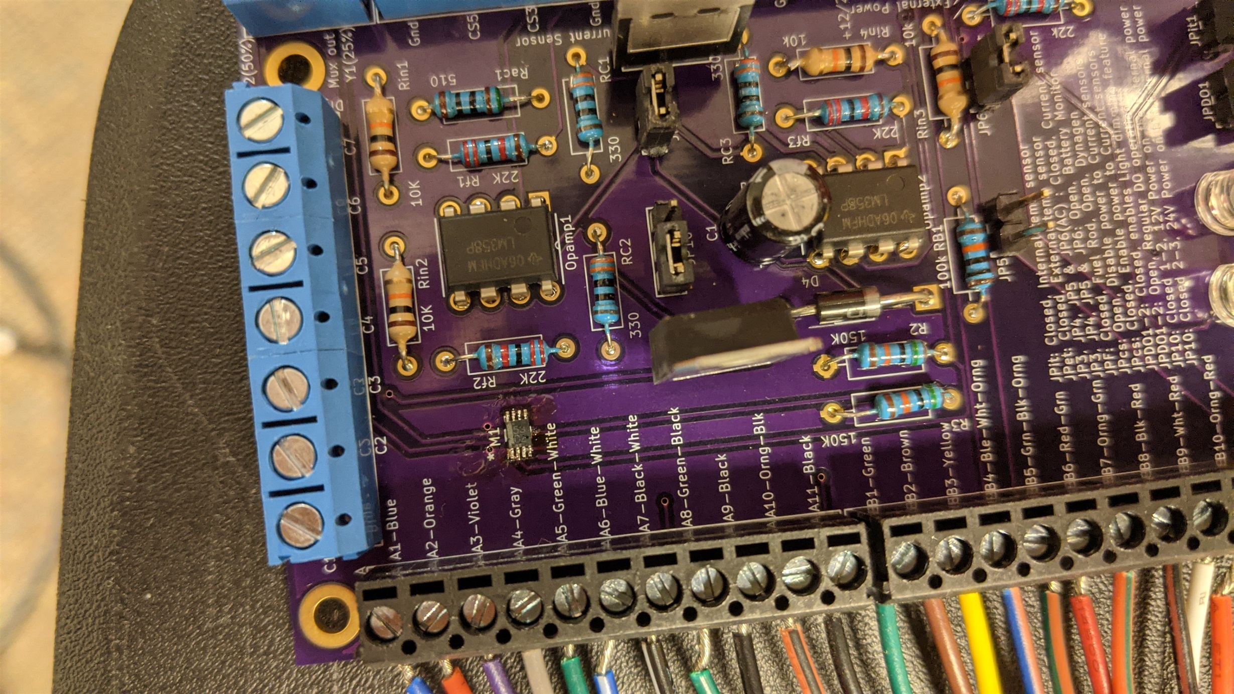
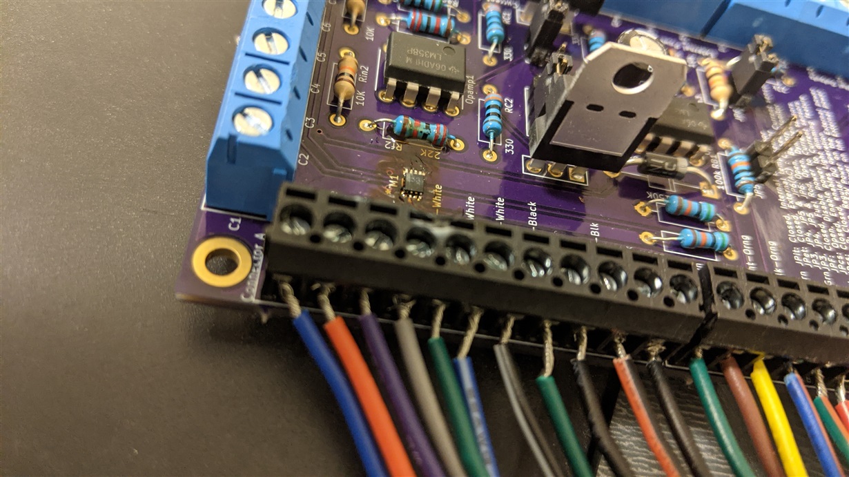
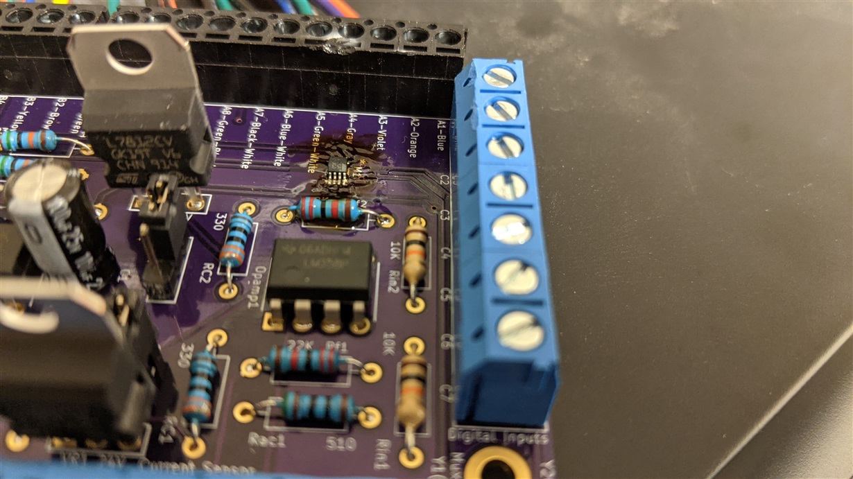
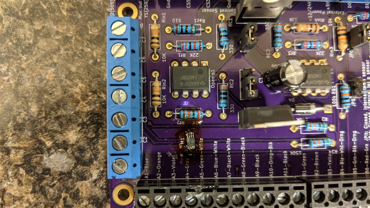
    Thank you for your question. How was the device soldered to the PCB? Based on the fact that Y1 and Y2 are consistently similar and unexpected values in this case, could you check if any pins are shorted together on the board? Could you provide a photo of the device on the board?

    What are the loading conditions on Y1 and Y2? Do you have a block diagram or schematic that you can share?

    Thank you,
    Kate

  • Please note that Y1/Y2 are not outputs and have no drive strength on their own. They are either connected to COM or disconnected, so their voltage is either 5 V or floating (undefined). It is not possible the measure the voltage of a floating pin. You get 0 V only if you add pull-down resistors; did your first experiment have them? What happens if you measure the voltage between the pins and VCC?

    Y1 = Inh NOR A; Y2 = Inh NOR (NOT A). Both functions can be implemented with the SN74LVC1G98.

  • Hello 

    Yes. I get that. Y1 and Y2 are connected to Comm which is 5V. I checked for shorts and didn't find any part from 3 and 4 which are both GND. The part that I received dint have the dot thing which would tell me which pin is PIN 1. So I contacted Digikey and they told me that the white one side is where PIN 1 is. I sent them pictures and they confirmed that the orientation is right. But now, I'm having second thoughts. 

    I have attached the picture of the part on my board. Please note, the bottom left is PIN 1. Could you please confirm if my orientation is right? I have also attached the schematic of the MUX. 

    A and Inh can be grounded when wanted. They are connected to open-collector outputs. 

  • Hi Varun,

    Thanks for sending the picture and schematic. It does look like there could be some solder between pins 1 and 2 (bottom left, as you say). If this is in fact a short in your system, INH and COM are tied together, which would cause INH to stay high and the switch to remain high impedance.

    As Clemens mentioned, if a signal path is off, such as when INH is high, Y1 and Y2 should not have any voltage (they are floating). So I'm not sure why you were able to measure 0.6V at these nodes with INH at 5V, unless something in your system is pulling these pins to that voltage.

    What is the U8 in your schematic?

    Thanks,
    Kate

  • Hello Kate, 

    I'll solder again tomorrow to be sure.

    Can you please confirm if the component orientation is correct? I mean, is PIN 1 of the component connected to PIN 1 of the footprint. PIN 1 of the footprint is bottom left when you look at the picture. 

    There is no dot kinda marking for pin 1 on the component as the datasheet says on page 3. 

    U8 is a 2 pin connector. I plan on connecting two wire which will go to other components that require 5 V to turn ON. So the MUX will control the operation of these components. Nothing is connected to that component at this point. I want to make sure I get 5V there first. So this is not the problem. 

    Varun R

  • Hi Varun, 

    Thanks for the additional information. Please see the diagram Clemens has posted for identification of 'pin 1' and orientation of the device.

    Let me know what you find after you re-solder the device. My recommendation is that you place a part you have not yet used on the board, just in case there was any damage done to the part previously soldered to the board.

    Could you send the measured voltages at all pins for each control state? Thanks!

    Best regards,
    Kate

  • Hello 

    Thanks, Clemens for confirming that. So Orientation is not the problem. As Kate suggested, I used a new component and soldered again. I measured the voltages at the pins of the component itself. The truth table is as follows:

    Inh A Y1 Y2
    5V 5V 0v  0v
    0V 0V 5V 0V
    0V 5V 5V 0V

    COM and VCC have always been at 5V. Not sure why Y1 is always 5V and Y2 is always at 0V (float). It's not switching essentially. 

    Note: Y1 is right next to VCC. I initially thought I might be measure Vcc instead of Y1 and thinking Y1 is 5V. But I made sure like 10 times. The probe was placed away from Vcc pin multiple times and I still got 5V. There is not short as well. I took multiple pictures to make sure. I have attached them to this reply. 

    It's progress but not there yet. 

    Thank you 

    Varun R

  • It works now .. 

    Thank you 

  • Hi Varun,

    I'm glad to hear it is working! Could you share the root cause of the issue and how you resolved it?

    Thanks,
    Kate

  • First MUX, something was wrong with it. 0.8V and 0.6 V are something that I can't explain. 

    Second MUX, I flipped the orientation as an experiment to see if it would work. It didn't. My first orientation was right. Clements confirmed it. 

    Third MUX. Too many soldiers at this point. Might have damaged the board a bit. After a few brushed of solder, it started to work. 

    I hope this helps. 

    Varun R