This thread has been locked.

If you have a related question, please click the "Ask a related question" button in the top right corner. The newly created question will be automatically linked to this question.

MUX506: MUX506

Part Number: MUX506
Other Parts Discussed in Thread: LMH6570, MUX507

hello,

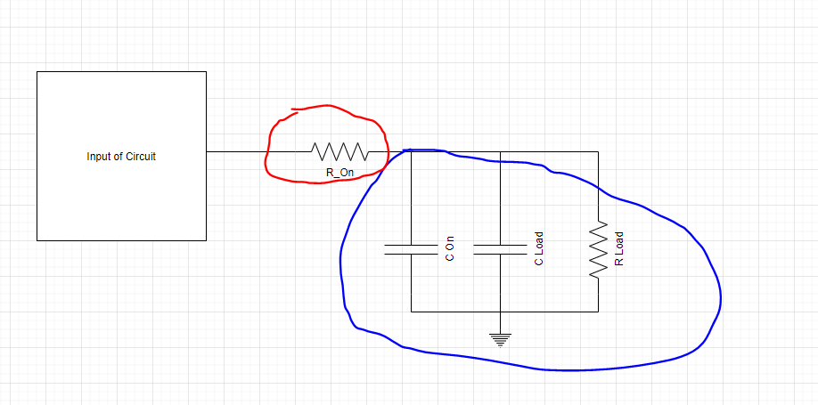
I am using MUX506 in my design.

I saw in the data sheet that the BW is 500Mhz. There was no indication if it is depends on what power supply?

In simulation I am seeing a difference between working with +/-5V and +/-10V.

What is really the Bandwidth at +/-5V power supplies.

Regards,

Giora


  • Hi Giora,

    Can  I ask what are the loading conditions of the mux are? Specifically I am looking for load capacitance and resistance as loading conditions will affect the system bandwidth. 

    Bandwidth that is listed online I am bit suspicious of since it isn't listed in the datasheet - however you can get a estimation of the bandwidth by looking at a simplified model of the mux: 

    Where bandwidth can be found by finding the transfer function for the load (in Blue)  - I have shown the process for finding the bandwidth:

    where the approximate corner (-3dB frequency) is going to be omega_c / 2pi. This is a bit of a liberal estimate and to be safe I'd add about 20 to 25% reduction (at worst case operating point - max temperature conditions) in bandwidth due to the device not being RC components but silicon. But the load does have a lot of influence on bandwidth so if you could provide that I can give you a rough estimate.

    If you have any other questions or any other needed clarification please let me know!

    Best,

    Parker Dodson

  • Hello Parker,

    Thanks.

    The load of the MUX is an input to LMH6570 terminated with 10K to ground. (see attached drawing)

    Regards,

    Giora

  • Hi Giora,

    So for this set up the following eq. circuit is used:

    Yellow = R_on which has a worst case spec at 12V single supply = 430 Ohms - this is the closest spec we have to +/-5V in the datasheet and it may be a bit higher at +/-5V.

    Green = C_on - the on capacitance this should be right around the typical value of 18pF

    Blue = Is the Input capacitance of the LMH6570 ~ 0.8pF 

    Red = This is the load resistance - it is a parallel combination of the Input resistance of the LMH6570 (5k) and the 10K Ohm Termination resistor  which is ~3.33k Ohms.

    This leads to the approximate -3dB point for worst On resistance is:

    This value is an approximation of the worst case R_ON value at a 12V single supply - which is the closest spec'd supply to +/- 5V - so worst case R_on may be a bit worse. However this is assuming you are operating at max temp conditions and using the full signal swing. These factors will also affect bandwidth so the effective bandwidth may be slightly higher than above depending on the nuances of the application. 

    When I simulate this in spice using passive elements I get the following AC response:

    Which has its corner frequency at ~16.71MHz. This is more accurate as this isn't the linear

    If this is a concern for your application - can you please share what your anticipated required signal bandwidth is going to be? Also if I could get the I/O signal range and expected operating temperature (ambient) -  That way I can see if we have a better fit that can suit the higher frequency signal or if the actual application may be able to handle higher frequencies than a worst case scenario.

    Please let me know!

    Best,

    Parker S. Dodson

  • Hello Parker,

    Thanks for the answer.

    1. In the simulation (25 C) I got  ~ 30MHz using +/- 7V for the supplies, Surely it is not the worst case. 

    2, Ambient Temp. will be ~ 50 Celsius degree.

    3. I need at least 40Mhz BW.

    So I was mislead by the "500Mhz BW".

    Regards,

    Giora 

  • Hi Giora,

    Do you have any flexibility in your design for higher supply rails to the Multiplexer? After looking through our portfolio I am worried you will have similar problems with our other 16:1 options. The higher on resistance at lower supply voltages are killing the bandwidth.

    If you can get the +/- 10V supplies you are at ~45MHz and possibly higher bandwidth if the signal swing is less than the +/- 10V. 16:1 multiplexers have a tendency to be lower bandwidth because the 16:1 configuration introduces a lot of parasitic capacitance which degrade bandwidth. Also our 16:1 multiplexers that can handle a bi-polar supply have higher on resistance at +/-5V. 

    I apologize for the 500MHz confusion - there was a mistake ; under optimal conditions the MUX507 (2 Channel 8:1 Device related to the MUX506) can hit 500MHz under optimal conditions (where this device can hit 240MHz under optimal conditions) and that is what is being displayed there. At +/-5V supplies the parts we have that operate at that voltage will not be working in optimal conditions.  

    If you need any more help please let me know!

    Best,

    Parker Dodson

  • Hi Parker,

    Thanks for your detailed answer.

    We are going to do as you suggested and bias the MUX with +24V and -5V.

    First measure indicates ~ 46Mhz.

    Is it OK to work with asymmetric voltages? 

    Regards,

    Giora

  • Hi Giora,

    You are welcome - I am glad I was able to help!

    Asymmetric supplies are okay as long as  10V <= VDD - VSS <= 36V and you are at 29V so it looks good to go!

    If you have any other questions please let me know!

    Best,

    Parker Dodson