This thread has been locked.

If you have a related question, please click the "Ask a related question" button in the top right corner. The newly created question will be automatically linked to this question.

Linker places entry point function address not exactly where requested

Part Number: TM4C1294NCPDT

HI All,

I'm trying to place my entry point function at address 0x11000.  Yet the linker consistently places it at 0x11001.  I get no warnings or errors during linking.

If I jump to 0x11000 (desired address), the processor crashes.

If I jump to 0x11001, the program runs properly so it appears that my entry point function is really at 0x11001.

I've included as much info as I could find to demonstrate the contradictions.

Thank you,

Peter

My linker file where I map my entry function to a section called 'myEntryPoint' and map it to address 0x11000.

SECTIONS
{
    .intvecs:   > 0x00010000

    .text   :   > FLASH
    .const  :   > FLASH
    .cinit  :   > FLASH
    .pinit  :   > FLASH
    .init_array : > FLASH
    .test	:	> FLASH

    .vtable :   > 0x20000000
    .data   :   > SRAM
    .bss    :   > SRAM
    .sysmem :   > SRAM
    .stack  :   > SRAM
    .nvv 	: 	> SRAM

    myEntryPoint
    {
        entryPoint.obj(.text)
    } > 0x11000
}

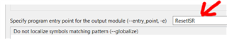
My linker configuration where I specify the name of my entry point, which is in the myEntryPoint.obj:

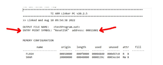
And sections of my map file, which has contradictory information as to the entry point:

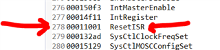
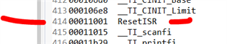
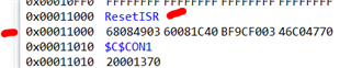
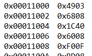
And finally, a snapshot of the actual memory after flashing the program via CCS:

  • Hello Peter,

    The correct start point is 0x11001. The device is Little Endian device meaning the least significant bits are being placed first. Therefore your entry point symbol needs to fetch the upper 16 bits from 0x11001 first and then the lower 16 bits from 0x11000.

    See Section 2.4.6 Data Storage of the device datasheet for more details.

    Best Regards,

    Ralph Jacobi

  • Hello Ralph,

    Thank you for taking the time to explain.

    If I understand correctly, can I make the statement (for an little endian processor):

    "Any .text segment that is explicitly mapped to an even address, ought to programmatically addressed by its next byte."

    I'm using the following example as a means to my head around the addressing.

    Thanks,

    Peter

    C code:

    int e1 = 0;
    void ResetISR(void)
    {
        e1++;
    
        __asm("    .global _c_int00\n"
              "    b.w     _c_int00");
    }

    assembly listing:

          66 00000000 4903              LDR       A2, $C$CON1           ; [DPU_V7M3_PIPE] |11|  ; [ORIG 16-BIT INS]
          67 00000002 6808              LDR       A1, [A2, #0]          ; [DPU_V7M3_PIPE] |11|  ; [ORIG 16-BIT INS]
          68 00000004 1C40              ADDS      A1, A1, #1            ; [DPU_V7M3_PIPE] |11|  ; [ORIG 16-BIT INS]
          69 00000006 6008              STR       A1, [A2, #0]          ; [DPU_V7M3_PIPE] |11|  ; [ORIG 16-BIT INS]

    Memory view:

  • Hello Peter,

    As long as the value held is expected to be a 32 byte value such as the next Program Counter value, an address value etc., yes.

    Best Regards,

    Ralph Jacobi

  • The device is Little Endian device meaning the least significant bits are being placed first.

    I think the explanation is that the Cortex-M CPU in the TM4C devices only supports THUMB mode.

    As explained by Pointers to functions in Thumb state it is the correct behaviour for pointers to functions in THUMB mode to have the least significant bit set.

  • Thanks you Chester and Ralph.

    I'm coming from the C28xxx world and this whole notion of THUMB mode in ARM's is new to me (and now I understand why the function pointers are addressed in an odd (get it?) manner).

    Here's another link to an explanation of THUMB mode that I found useful (if anybody else in the future is reading this):

    https://stackoverflow.com/questions/10638130/what-is-the-arm-thumb-instruction-set

    Thanks again for your help and time,

    Peter