This thread has been locked.

If you have a related question, please click the "Ask a related question" button in the top right corner. The newly created question will be automatically linked to this question.

bricked XDS220 due to firmware update on OSX; trying to recover

Other Parts Discussed in Thread: AM1802

I have an XDS220 (PN 516300-0001, serial X2D_1401037) that I managed to brick by trying to perform a firmware update on OSX. Same symptoms as shown in this thread, but I can't seem to get CCS (on Linux or Windows) to connect to it with an XDS100v2. I have connected (and verified) TDI, TDO, TMS, TCK, RTCK, TRST, GND and 3.3V, but when I test the connection with CCS, it says there's a far-end break detected. If I use OpenOCD it actually connects and I can stop/step/etc. the processor, but loading the fw1009.bin to location 0x80010000 and trying to resume execution at the same address doesn't appear to work.

By "doesn't appear to work" what I mean is that the processor seems to run, but I don't see the USB device appear and if I halt the processor, it seems to be at the same endless loop instruction that it was at when I first connected. I’ve also played with TCK clock speeds, using RTCK or ignoring it… nothing seems to help.

> reset halt
JTAG tap: omapl138.jrc tap/device found: 0x1b7d102f (mfg: 0x017 (Texas Instruments), part: 0xb7d1, ver: 0x1)
JTAG tap: omapl138.etb enabled
JTAG tap: omapl138.arm enabled
target halted in ARM state due to debug-request, current mode: System
cpsr: 0xa00000df pc: 0x800016c8
MMU: disabled, D-Cache: disabled, I-Cache: disabled
NOTE! DCC downloads have not been enabled, defaulting to slow memory writes. Type 'help dcc'.

> omapl138.arm curstate
halted

> reg
===== ARM registers
(0) r0 (/32): 0xa00000df (dirty)
(1) r1 (/32): 0xe1500001 (dirty)
(2) r2 (/32): 0xdafffffc (dirty)
(3) r3 (/32): 0xe59f0044 (dirty)
(4) r4 (/32): 0xe59f1044 (dirty)
(5) r5 (/32): 0xe2400c05 (dirty)
(6) r6 (/32): 0xe321f0d3 (dirty)
(7) r7 (/32): 0xe1a0d000 (dirty)
(8) r8 (/32): 0xe2400008 (dirty)
(9) r9 (/32): 0xe321f0df (dirty)
(10) r10 (/32): 0xe1a0d000 (dirty)
(11) r11 (/32): 0xe59f0054 (dirty)
(12) r12 (/32): 0xe59f1054 (dirty)
(13) sp_usr (/32): 0xe3a02000 (dirty)
(14) lr_usr (/32): 0xe4802004 (dirty)
(15) pc (/32): 0x800016c8 (dirty)
(16) r8_fiq (/32)
(17) r9_fiq (/32)
(18) r10_fiq (/32)
(19) r11_fiq (/32)
(20) r12_fiq (/32)
(21) sp_fiq (/32)
(22) lr_fiq (/32)
(23) sp_irq (/32)
(24) lr_irq (/32)
(25) sp_svc (/32)
(26) lr_svc (/32)
(27) sp_abt (/32)
(28) lr_abt (/32)
(29) sp_und (/32)
(30) lr_und (/32)
(31) cpsr (/32): 0xa00000df
(32) spsr_fiq (/32)
(33) spsr_irq (/32)
(34) spsr_svc (/32)
(35) spsr_abt (/32)
(36) spsr_und (/32)
(37) sp (/32)
(38) lr (/32)
===== EmbeddedICE registers
===== etm registers
===== etb registers

> load_image /home/andrew/ti/ccs1230/ccs/ccs_base/common/uscif/xds2xx/xds220_firload_image /home/andrew/ti/ccs1230/ccs/ccs_base/common/uscif/xds2xx/xds220_firmware_v1009.bin 0x80010000 bin
92814 bytes written at address 0x80010000
downloaded 92814 bytes in 2.201913s (41.164 KiB/s)

> mdw 0x80010000 0x20         
0x80010000: ea000004 40000000 4000033c 4000033c 40016a90 4004c3c8 e59f0098 e321f0db 
0x80010020: e1a0d000 e2400008 e321f0d7 e1a0d000 e2400008 e321f0d1 e1a0d000 e2400008 
0x80010040: e321f0d2 e1a0d000 e2400c05 e321f0d3 e1a0d000 e2400008 e321f0df e1a0d000 
0x80010060: e59f0054 e59f1054 e3a02000 e4802004 e1500001 dafffffc e59f0044 e59f1044 

> resume 0x80010000

... wait, nothing showing up on USB ...

> halt
target halted in ARM state due to debug-request, current mode: System
cpsr: 0xa00000df pc: 0x800015fc
MMU: disabled, D-Cache: disabled, I-Cache: disabled

> reg
===== ARM registers
(0) r0 (/32): 0xffffffff (dirty)
(1) r1 (/32): 0x00000004
(2) r2 (/32): 0xffffffff
(3) r3 (/32): 0xffffffff
(4) r4 (/32): 0x80000000
(5) r5 (/32): 0xe2400c05
(6) r6 (/32): 0xe321f0d3
(7) r7 (/32): 0x00000000
(8) r8 (/32): 0xe2400008
(9) r9 (/32): 0xe321f0df
(10) r10 (/32): 0x80000aa0
(11) r11 (/32): 0x80003100
(12) r12 (/32): 0x00000001
(13) sp_usr (/32): 0x800030ec
(14) lr_usr (/32): 0x8000157c
(15) pc (/32): 0x800015fc (dirty)
(16) r8_fiq (/32)
(17) r9_fiq (/32)
(18) r10_fiq (/32)
(19) r11_fiq (/32)
(20) r12_fiq (/32)
(21) sp_fiq (/32)
(22) lr_fiq (/32)
(23) sp_irq (/32)
(24) lr_irq (/32)
(25) sp_svc (/32)
(26) lr_svc (/32)
(27) sp_abt (/32)
(28) lr_abt (/32)
(29) sp_und (/32)
(30) lr_und (/32)
(31) cpsr (/32): 0xa00000df
(32) spsr_fiq (/32)
(33) spsr_irq (/32)
(34) spsr_svc (/32)
(35) spsr_abt (/32)
(36) spsr_und (/32)
(37) sp (/32)
(38) lr (/32)
===== EmbeddedICE registers
===== etm registers
===== etb registers

I have also tried manually setting PC and SP to 0x80010018 and 0x40000000 respectively and resuming that way, but with the same results.

I'm quite sure I could recover this if I could only get the AM1802 to execute the code I've loaded. I have two questions:

1) How do I troubleshoot/resolve the "SC_ERR_CTL_CBL_BREAK_FAR" (-183) error in CCS? There isn't much info online and what is there is generic. I know the connections are good because OpenOCD can talk to the device.

2) What am I missing which is preventing me from getting the AM1082 from doing what I need via OpenOCD?

  • Hello Andrew,

    It sounds like the XDS220 is the device with the issue? (as opposed to the AM1802? I am not super clear on why the AM1802 is being discussed)

    I am sending your question over to the CCS team to comment.

    Regards,

    Nick

  • Hello,

    1) How do I troubleshoot/resolve the "SC_ERR_CTL_CBL_BREAK_FAR" (-183) error in CCS? There isn't much info online and what is there is generic. I know the connections are good because OpenOCD can talk to the device.

    The "cable break far" error indicates that there is some connection issue between the device and when the debug probe connects to the JTAG header on the target board. 

    For more details on the error, please see the section under "Cable break" in the below document:

    https://dev.ti.com/tirex/explore/node?node=A__ANoamrIZPWD2-6T-NDDWGg__ccs_devtools__FUz-xrs__LATEST

    Also try other suggestions such as lowering TCLK as mentioned in the above document

    2) What am I missing which is preventing me from getting the AM1082 from doing what I need via OpenOCD?

    I can't provide much suggestions regarding OpenOCD. Nick, can you help with this part? I assume the target device is an AM1802.

    Thanks

    ki

  • It sounds like the XDS220 is the device with the issue? (as opposed to the AM1802? I am not super clear on why the AM1802 is being discussed)

    Re-flash the firmware of onboard XDS200 units: contains:

    In case the XDS200 unit got its firmware corrupt, it can be re-flashed using an external XDS Debug Probe that is compatible with the AM1802 device present on the XDS200 design

    I.e. Andrew might be trying to recover the XDS220 by using a different debug probe to connect to the AM1802 within the bricked XDS220.

    I'm assuming that a XDS220 which is an isolated probe uses the same AM1802 as the XDS200 which isn't isolated.

  • My apologies for not being clearer.

    It is the XDS220 which is bricked. The XDS220 uses an AM1802 internally. It is the internal debug interface on the card edge that I have connected to an XDS100v2. I am trying to use the XDS100v2 to unbrick the XDS220 through the XDS220's internal card edge debug interface.

    CCS complains that there's a "far end cable break" when I click the test button, but I have verified and re-verified the wiring between the XDS100v2 and the card edge debug connector inside the XDS220 and I can see no break. I have TDI, TDO, TMS, TCK, RTCK, TRST, GND and 3.3V wired up, as per the original (closed, locked) thread, tried different JTAG clock frequencies (100kHz all the way up to 10MHz including the default "adaptive up to 1MHz"), but the issue persists.

    If I close CCS and instead use OpenOCD to access the XDS100v2 I can connect to the XDS220's internal AM1802 just fine. I can see registers, dump memory, control code execution using OpenOCD. If I load the v1009 binary firmware image into 0x80010000 I can see the loaded image data, and I can use "resume 0x80010000" or set IP/SR to 0x80010000/0x40000000 and try to resume, but I cannot see the XDS220 show up on the USB port of the computer, which is what the video in the original, locked thread shows.

    I believe I'm missing something which is preventing CCS from being able to verify the XDS100v2's connection to the XDS220, but the information on what this specific error means is vague and is basically "check wiring" which I've done (and redone, and redone). OpenOCD seems to have no issue so I am confident that the electrical wiring is sound. My best guess is that I am missing a step that CCS is doing behind the scenes. Uploading the firmware, issuing a hardware reset, setting IP to 0x8001000 and telling the XDS220's AM1802 processor to resume doesn't seem to be enough which is why I'm asking here.

    Is there any specific additional step I must to to make the AM1802 internal to the XDS220 execute the firmware I've loaded into RAM? Some ICEPICK or CPU state I'm unaware of?

    Failing that, how can I get more information about WHY CCS is unhappy with the connection? As mentioned, I'm quite certain that the electrical connection between the XDS100v2 and the XDS220 is sound, because OpenOCD is having no trouble talking to the ARM9. I can run the `dbgjtag` command manually and if I don't include the `-S integrity` option, it completes without error:

    ~/ti/ccs1230/ccs/ccs_base/common/uscif/dbgjtag -f ~/.ti/ccs1230/0/0/BrdDat/testBoard.dat -rv -o -F inform,logfile=yes -S pathlength 
    
    -----[Print the board config pathname(s)]------------------------------------
    
    /home/andrew/.ti/ccs1230/0/0/BrdDat/testBoard.dat
    
    -----[Print the reset-command software log-file]-----------------------------
    
    This utility has selected a 100/110/510 class product.
    This utility will load the adapter 'libjioserdesusb.so'.
    The library build date was 'Mar 10 2023'.
    The library build time was '17:24:20'.
    The library package version is '9.11.0.00128'.
    The library component version is '35.35.0.0'.
    The controller does not use a programmable FPGA.
    The controller has a version number of '4' (0x00000004).
    The controller has an insertion length of '0' (0x00000000).
    This utility will attempt to reset the controller.
    This utility has successfully reset the controller.
    
    -----[Print the reset-command hardware log-file]-----------------------------
    
    The scan-path will be reset by toggling the JTAG TRST signal.
    The controller is the FTDI FT2232 with USB interface.
    The link from controller to target is direct (without cable).
    The software is configured for FTDI FT2232 features.
    The controller cannot monitor the value on the EMU[0] pin.
    The controller cannot monitor the value on the EMU[1] pin.
    The controller cannot control the timing on output pins.
    The controller cannot control the timing on input pins.
    The scan-path link-delay has been set to exactly '0' (0x0000).
    
    -----[The log-file for the JTAG TCLK output generated from the PLL]----------
    
    There is no hardware for programming the JTAG TCLK frequency.
    
    -----[Measure the source and frequency of the final JTAG TCLKR input]--------
    
    There is no hardware for measuring the JTAG TCLK frequency.
    
    -----[Perform the standard path-length test on the JTAG IR and DR]-----------
    
    This path-length test uses blocks of 64 32-bit words.
    
    The JTAG IR instruction path-length was not recorded.
    

    If I add the `-S integrity` option (which is what CCS's GUI is doing with the "Test" button, I get the same SC_ERR_CTL_CBL_BREAK_FAR error:

    $ ~/ti/ccs1230/ccs/ccs_base/common/uscif/dbgjtag -f ~/.ti/ccs1230/0/0/BrdDat/testBoard.dat -rv -o -F inform,logfile=yes -S pathlength -S integrity
    
    -----[Print the board config pathname(s)]------------------------------------
    
    /home/andrew/.ti/ccs1230/0/0/BrdDat/testBoard.dat
    
    -----[Print the reset-command software log-file]-----------------------------
    
    This utility has selected a 100/110/510 class product.
    This utility will load the adapter 'libjioserdesusb.so'.
    The library build date was 'Mar 10 2023'.
    The library build time was '17:24:20'.
    The library package version is '9.11.0.00128'.
    The library component version is '35.35.0.0'.
    The controller does not use a programmable FPGA.
    The controller has a version number of '4' (0x00000004).
    The controller has an insertion length of '0' (0x00000000).
    This utility will attempt to reset the controller.
    This utility has successfully reset the controller.
    
    -----[Print the reset-command hardware log-file]-----------------------------
    
    The scan-path will be reset by toggling the JTAG TRST signal.
    The controller is the FTDI FT2232 with USB interface.
    The link from controller to target is direct (without cable).
    The software is configured for FTDI FT2232 features.
    The controller cannot monitor the value on the EMU[0] pin.
    The controller cannot monitor the value on the EMU[1] pin.
    The controller cannot control the timing on output pins.
    The controller cannot control the timing on input pins.
    The scan-path link-delay has been set to exactly '0' (0x0000).
    
    -----[The log-file for the JTAG TCLK output generated from the PLL]----------
    
    There is no hardware for programming the JTAG TCLK frequency.
    
    -----[Measure the source and frequency of the final JTAG TCLKR input]--------
    
    There is no hardware for measuring the JTAG TCLK frequency.
    
    -----[Perform the standard path-length test on the JTAG IR and DR]-----------
    
    This path-length test uses blocks of 64 32-bit words.
    
    The JTAG IR instruction path-length was not recorded.
    
    -----[Perform the Integrity scan-test on the JTAG IR]------------------------
    
    This test will use blocks of 64 32-bit words.
    This test will be applied just once.
    
    Do a test using 0xFFFFFFFF.
    Scan tests: 1, skipped: 0, failed: 0
    
    -----[An error has occurred and this utility has aborted]--------------------
    
    This error is generated by TI's USCIF driver or utilities.
    
    The value is '-183' (0xffffff49).
    The title is 'SC_ERR_CTL_CBL_BREAK_FAR'.
    
    The explanation is:
    The controller has detected a cable break far-from itself.
    The user must connect the cable/pod to the target.
    

    Unfortunately this tool does not give much more debug information, or perhaps I'm unaware of how to invoke or interpret it.

    For completeness, here is the testBoard.dat file that CCS generated:

    $ cat ~/.ti/ccs1230/0/0/BrdDat/testBoard.dat 
    # config version=3.5
    $ sepk
      pod_drvr=libjioserdesusb.so
      pod_port=0
    $ /
    $ product
      title="Texas Instruments XDS100v2 USB"
      alias=TI_XDS100v2_USB
      name=FTDI_FT2232
    $ /
    $ ftdi_ft2232
      usb_vid=0x0403
      usb_pid=0xa6d0
      gpio_l0="TRSTn,Active_Low"
      gpio_l1="EMU_Pin_Enable,Active_Low"
      gpio_l2="EMU_Pin_0,Active_Low"
      gpio_l3="Adaptive_Clock,Active_High"
      gpio_h0="SRSTn,Active_High"
      gpio_h1="SRSTn_In,Active_Low"
      gpio_h2="Power_Loss_Detect,Active_Low"
      gpio_h3="Power_Loss_Reset,Active_High"
      gpio_h4="EMU_Pin_1,Active_Low"
      gpio_h5="Cable_Disconnect,Active_High"
      gpio_h6="Loopback,Active_High"
    $ /
    $ uscif
      tdoedge=FALL
      jtagboot_mode=disable
      jtagboot_value=hiz
      powerboot_mode=disable
      powerboot_value=hiz
      tclk_program=ADAPTIVE
      tclk_frequency=4.0MHz
      loopback_mode=disable
      loopback_value=disable
    $ /
    @ icepick_c family=icepick_c irbits=6 drbits=1 subpaths=3 systemresetsupported=1 systemresetwhileconnected=1
      & subpath_2 address=19 default=no custom=no force=yes pseudo=no cancelreset=0x0
        @ etb11_0 family=etb11 irbits=4 drbits=1
      & subpath_1 address=18 default=no custom=no force=yes pseudo=no cancelreset=0x0
        @ arm9_0 family=arm9xx irbits=4 drbits=1
      & subpath_0 address=17 default=no custom=no force=yes pseudo=no cancelreset=0x0
        @ pru_1 family=pru irbits=0 drbits=0
        @ pru_0 family=pru irbits=0 drbits=0
      & /
    # /
    

  • Hello Ki,

    I mentioned in my original post that I have looked at the page you linked, however reading it again I noticed this:

    Another possible cause of a "cable break far-from itself" could be that the TVRef signal (pin 5) is pulled up to the IO voltage, or TDIS (pin 4) is pulled-down to ground. TVRef should be connected to the IO voltage through a small current limiting resistor.

    What exactly should the "small value resistor" value be? A couple hundred ohms perhaps? I do have it connected directly to the IO voltage (3.3V, pin 14 on the XDS220 internal debug card edge connector). It's not "pulled up", it is directly connected. I do *not* have TDIS connected to anything though; I will ground this connection as per https://software-dl.ti.com/ccs/esd/documents/xdsdebugprobes/emu_xds_target_connection_guide.html and try again.

  • CCS complains that there's a "far end cable break" when I click the test button, but I have verified and re-verified the wiring between the XDS100v2 and the card edge debug connector inside the XDS220 and I can see no break

    Can you try running <ccs_install_root>/ccs/ccs_base/common/uscif/xds100serial and see if under OSX a generic FT2232 serial-to-USB adaptor is present?

    With CCS under Linux have found that unless you specific a XDS100v2 by serial number CCS can use a generic FT2232 serial-to-USB adaptor, resulting in "The controller has detected a cable break far-from itself".

    See Linux 64 OS on a machine with a C2000 processor and XDS100v1 for an example.

  • You're correct, Chester; I bricked my XDS220 (not an ISO unit, just XDS220 from Spectrum Digital, whose website is unfortunately long gone). The part number of my specific XDS220 probe is 516300-0001, and it is not isolated.

  • Hello, Chester,

    The XDS100v2 is detected correctly (I did have an issue before but fixed it by updating the udev rules as per the install documentation):

    $ ~/ti/ccs1230/ccs/ccs_base/common/uscif/xds100serial 
    Scanning for XDS100 emulators...
    
    VID/PID    Type            Serial #    Description
    0403/a6d0  XDS100v1/v2     SD05YSNA    Texas Instruments Inc.XDS100 Ver 2.
    

    At this point I'm almost 100% certain the issue with CCS is because I do not have pin 4 (TDIS) connected to anything. I will ground it and report back. With a little luck you'll hear my whoop of success/relief where ever you happen to be in the world. :-)

  • The XDS100v2 pin 4 NOT being connected to ground was the issue for the CCS "far break" error. I am now past that error, and have been able to successfully recover my XDS220. 

    There are a couple of things that the original thread did not specify and/or did not make clear:

    • TDI, TDO, TMS, TCK, RTCK, TRST, GND and 3.3V is not enough. TDIS (pin 4 on the XDS100v2 14-pin debug connector) MUST be grounded or you will get the "SC_ERR_CTL_CBL_BREAK_FAR" (-183)" error. Since OpenOCD doesn't care about this extraneous signal, it was unaffected.
    • The correct binary to load into RAM is the xds200_firmware_v1009.bin file. NOT the xds220_firmware_v1009.bin or xds220_firmware_iso_v1009.bin files. This is both counterintuitive and confusing. You must load the xds200 firmware file, NOT the xds220 firmware file, even if you have an XDS220.

    I suspect that if I was loading the XDS200 firmware file in OpenOCD it would have worked, because loading either of the XDS220 firmware files in CCS had the same result as OpenOCD.

    $ ./xds2xx_conf get xds2xxu 0
    boardRev=1
    ipAddress=192.168.77.36
    ipConfig=dhcp
    ipGateway=0.0.0.0
    ipNetmask=0.0.0.0
    productClass=XDS2XX
    productName=XDS220
    serialNum=S200-000E9903975B
    swRev=1.0.0.9
    hostCPU=AM1802
    emuCtrlType=Bit bang
    extMemType=SDRAM
    portUSB=true
    portENET=true
    portWIFI=false
    portRS232=false
    EnableUSBSerial=false
    CurrentMeasure=true
    

    The final thing that I was unaware of is that the XDS220 I have is perhaps an iso after all, despite not being clearly marked as such. This is perhaps why the update script failed originally.

    For posterity, here are the steps I used:

    1. connect XDS100v2 (or any other JTAG tool you want) to the internal edge connector. Samtec HSEC8-110-01-L-DV was the connector I used because I didn't want to solder to the board.
    2. TDI, TDO, TMS, TCK, RTCK, TRST, GND and 3.3V must be connected. Additionally, if you're using CCS, the "target disconnect" signal (pin 4 on the TI 14-pin debug connector) must be grounded or you'll get a "far end break" error.
    3. If using OpenOCD, you can use the Beaglebone target definition as it's also using an AM1802.
    4. Connect to the target, load the xds200_firmware_v1009.bin to RAM starting at 0x80010000. Note that this is the XDS200 file, not either the XDS220 or XDS220-ISO files. They will not work. You must use the XDS200 file.
    5. reset the ARM9, and either set PC to 0x80010000 or resume execution starting at 0x80010000. If everything went well, the XDS220 composite USB device will show up in your USB device list.
    6. use the xds2xx_conf program to update the firmware to the XDS220 or XDS220_ISO firmware.
    7. use the xds2xx_conf program to reboot the XDS220. This takes about a minute but the USB device should show up again after.
    8. use the xds2xx_conf program to program the CPLD file. This also takes a minute or so.
    9. use the xds2xx_conf program to reboot the XDS220 again. It should now be updated and working correctly.

    One other small note is that it looks like the xds2xx_conf utility likes to be run from the directory that the firmware files are in. Updating the firmware by specifying the full path worked fine, but programming the CPLD file gave an odd "file app_cpld.bin doesn't exist" error. I never specified that name, I specified the xds220_cpld_iso_v1009.xvsf file with the full path. Rebooting the XDS220 and running the script from the ~/ti/ccs1230/ccs/ccs_base/common/uscif/xds2xx directory cleared up the issue, but this is not intuitive.

    My specific interconnection between the edge connector on the XDS220 and the TI 14 pin connector on the XDS100v2 is as follows:

    Signal Name

    XDS220 Edge

    XDS100v2 Header
    TRST 1 2
    TMS 3 1
    TDI 5 3
    TDO 7 7
    GND 11 8,10,12
    RTCK 13 9
    TCK 15 11
    3.3V 14 5
    TDIS - 4 (connect to ground)

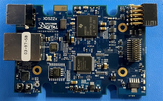
    xds220 top side internal photo