I am remotely accessing to a machine which is connected to a C6678L via XDS100 USB emulator. I am specifying the emulator as XDS100v2 in the target configurations. When I try to Run as Debug I get the following error:
IcePick_D: Error connecting to the target:
(Error -151 @ 0x0)
This utility failed to open the adapter for a custom emulator.
The adapter returned an error.
(Emulation package 5.0.520.0)
This is another error one of my colleague is getting when he tries from a different system:
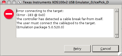
Error connecting to the target:
(Error -183 @ 0x0)
The controller has detected a cable break far-from itself.
The user must connect the cable/pod to the target.
(Emulation package 5.0.520.0)
I am using CCS 5.1 on 32 bit Ubuntu 10.04. Please help me in solving the error.
Thank you
Sayan


 :
: