This thread has been locked.

If you have a related question, please click the "Ask a related question" button in the top right corner. The newly created question will be automatically linked to this question.

UCD3138OL40EVM-032: How to achieve serial communication on UCD3138OL40EVM-032

Part Number: UCD3138OL40EVM-032
Other Parts Discussed in Thread: UCD3138, UCD3138064

Tool/software:

Dear UCD expert,

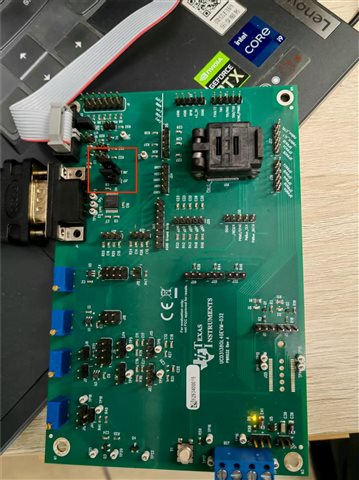
Hello, I just came into contact with the UCD3138 chip recently, I want to test the serial port function, the relevant code is shown in the figure. Using "memory debug", you can see that the data is sent to the serial port register, but no data is sent out when debugging with the serial port tool, and there is no waveform when measuring the TX pin of uart with an oscilloscope. I wonder if it's a problem with my gpio settings or if there's a problem with my hardware connection. I hope you can help answer, thank you.

Regards.

void init_uart0(void)
{
    volatile Uint32 rx_byte0; //volatile to make warning go away about set but not read

    Uart0Regs.UARTCTRL3.bit.SW_RESET = 0; //software reset while initializing UART

    Uart0Regs.UARTCTRL0.bit.DATA_SIZE = 7; //8 bits
    Uart0Regs.UARTCTRL0.bit.STOP = 1; //2 stop bits
    Uart0Regs.UARTCTRL0.bit.SYNC_MODE = 1; //asynchronous mode

    Uart0Regs.UARTHBAUD.all = 0;
    Uart0Regs.UARTMBAUD.all = 0;
    Uart0Regs.UARTLBAUD.all = 49; //for 38400 //47 for control board, 44 for open loop

    Uart0Regs.UARTRXST.bit.RX_ENA = 1 ;//enable RX

    Uart0Regs.UARTTXST.bit.TX_ENA = 1;//enable TX

    Uart0Regs.UARTINTST.all = 0xff; //these two statements are supposed to clear the status bits
    Uart0Regs.UARTINTST.all = 0;

    rx_byte0 = Uart0Regs.UARTRXBUF.bit.RXDAT; //clear RXRDY flag

    Uart0Regs.UARTIOCTRLTX.bit.IO_FUNC = 1; //enable transmit pin
    Uart0Regs.UARTIOCTRLRX.bit.IO_FUNC = 1; //enable receive pin

    Uart0Regs.UARTCTRL3.bit.CLOCK = 1; //internal clock select;
    Uart0Regs.UARTCTRL3.bit.SW_RESET = 1; //software reset released UART init done?

    Uart0Regs.UARTIOCTRLSCLK.bit.IO_FUNC = 0; //disable external clock for UART.

    Uart0Regs.UARTTXBUF.all = '\n'; //put out a byte to get things started.
}

void char_out(char data)
{
    while(Uart0Regs.UARTTXST.bit.TX_RDY == 0)
    {
        //do nothing while waiting for data to transmit.
    }
    Uart0Regs.UARTTXBUF.all = data; //put out a byte
}

void main()
{
    // enable JTAG
    MiscAnalogRegs.IOMUX.all = 0;

    //---------------------------------------------------------------------------
    // IMPORTANT: READ BELOW, OR CODE MAY NOT EXECUTE CORRECTLY
    //---------------------------------------------------------------------------
    // tie pin FAULT3 to ground for normal operation
    // tie pin FAULT3 to 3.3V to clear checksum
    if(GioRegs.FAULTIN.bit.FLT2_IN == 1)
    {
        clear_integrity_word();
    }

    #if (UCD3138|UCD3138064)
        MiscAnalogRegs.CLKTRIM.bit.HFO_LN_FILTER_EN = 0;
        MiscAnalogRegs.CSTRIM.bit.RESISTOR_TRIM =23; //28;
    #endif

    init_pmbus(0x58); // initialize PMBus handler
    init_uart0();
    for(;;)
    {
        pmbus_handler();
        char_out('1');
    }

}
  • Hello Zhang,

    Please see the following example code and PowerPoint on using the UART with the UCD3138 open loop EVMs. This example code reads in data from the UART and uses the data to set the DPWM event 2. 

    UCD31xx DPWM Open Loop - Lab 2.ppt

    https://e2e.ti.com/cfs-file/__key/communityserver-discussions-components-files/81/uart02_5F00_openloopdpwm.7z

    Your setup has the UART pins directly connected to your USB coms port. That should work as well. However, our example utilizes the RS-232 connector on the open loop EVM. Something like the following RS-232 adapter will work: https://a.co/d/cZ1qHYk. Our setup uses an RS-232 adapter and PuTTY (https://www.putty.org/) to open a serial port.

    As a note, you can insert C code in E2E by going to Insert --> Code and selecting C in the dropdown.

    Regards,

    Jonathan Wong

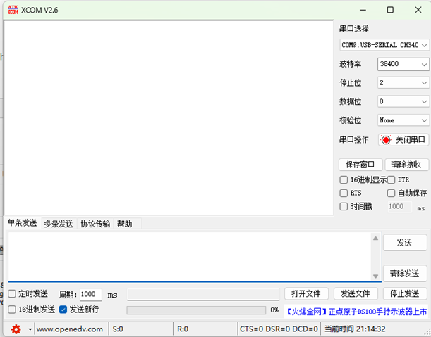
  •   Thank you very much for your answer, I used your code and tried RS232, but I still can't do serial communication. There is no signal on the TX pin at all.

  • Hi Zhang,

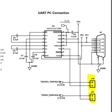
    Why do you have the jumper wires connecting directly to the UART pins? As long as you connect use jumper shunts on J16 and J17, the connection will automatically go to the UART pin on the UCD3138. I think all you need to do is short J16 and J17 headers and the UART should work.

    Can you also enable the UART interrupt and see if the interrupt flag is triggered? That will let you know if an UART data is received.

    Lastly, can you probe the UART signals on an oscilloscope or logic analyzer? Just place a probe on J16 and J17 to make sure you are actually receiving and transmitting UART data.

    Best,

    Jonathan Wong

  • Hi Jonathan,

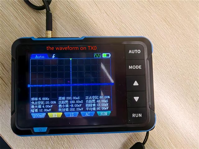
    I connect use jumper shunts on J16 and J17, but it still can't work. I tested the waveform on the TX pin with an oscilloscope and there was no output at all. I feel like the uart function doesn't work at all.

    Best,

    Ziang Zhang

  • Hello Ziang,

    I will provide a response tomorrow. I suspect it may be due to you using the 40-pin version when the code is meant for the 64-pin version.

    Regards,

    Jonathan Wong

  • Hello Ziang,

    Try using this UART handler from the LLC Firmware https://www.ti.com/tool/UCD3138FW_LLC

    //###########################################################################
    //
    // FILE:    uart.c
    //
    // TITLE:
    //
    // NOTES:
    //  1)
    //###########################################################################
    //
    //  Ver  | dd mmm yyyy | Who  		| Description of changes
    // ======|=============|============|========================================
    //  00 	   08 28 2015 	 HPCS
    //
    //  Texas Instruments, Inc
    //  Copyright Texas Instruments 2008. All rights reserved.
    //###########################################################################
    
    #include "cyclone_device.h"
    #include "software_interrupts.h"
    #include "system_defines.h"
    #include "variables.h"
    
    
    #define BAUD_RATE 4800
    #define BAUD_RATE_VALUE   (15625000/ (8 * ( BAUD_RATE + 1)) )
    #define BAUD_RATE_VALUE_L (BAUD_RATE_VALUE & 0xFF)
    #define BAUD_RATE_VALUE_M ( BAUD_RATE_VALUE >> 8 )
    
    void init_uart0(void)
    {
    	volatile Uint32 rx_byte0; //volatile to make warning go away about set but not read
    
    	Uart0Regs.UARTCTRL3.bit.SW_RESET = 0; //software reset while initializing UART
    
    	Uart0Regs.UARTCTRL0.bit.DATA_SIZE = 7; //8 bits
    	Uart0Regs.UARTCTRL0.bit.STOP = 1; //2 stop bits
    	Uart0Regs.UARTCTRL0.bit.SYNC_MODE = 1; //asynchronous mode
    
    	Uart0Regs.UARTHBAUD.all = 0;
    	Uart0Regs.UARTMBAUD.all = BAUD_RATE_VALUE_M;
    	Uart0Regs.UARTLBAUD.all = BAUD_RATE_VALUE_L;  //for 38400 //47 for control board, 44 for open loop
    
    	Uart0Regs.UARTRXST.bit.RX_ENA = 1 ;//enable RX
    
    	Uart0Regs.UARTTXST.bit.TX_ENA = 1;//enable TX
    
    	Uart0Regs.UARTINTST.all = 0xff;  //these two statements are supposed to clear the status bits
    	Uart0Regs.UARTINTST.all = 0;
    
    	rx_byte0 = Uart0Regs.UARTRXBUF.all; //clear RXRDY flag
    
    	Uart0Regs.UARTIOCTRLTX.bit.IO_FUNC = 1; //enable transmit pin
    	Uart0Regs.UARTIOCTRLRX.bit.IO_FUNC = 1; //enable receive pin
    
    	Uart0Regs.UARTCTRL3.bit.CLOCK = 1; //internal clock select;
    	Uart0Regs.UARTCTRL3.bit.SW_RESET = 1; //software reset released UART init done?
    
    	Uart0Regs.UARTIOCTRLSCLK.bit.IO_FUNC = 0; //disable external clock for UART.
    
    	Uart0Regs.UARTTXBUF.all = '\n'; //put out a byte to get things started.
    }
    
    void init_uart1(void)
    {
    	volatile Uint32 rx_byte1; //volatile to make warning go away about set but not read
    
    	Uart1Regs.UARTCTRL3.bit.SW_RESET = 0; //software reset while initializing UART
    
    	Uart1Regs.UARTCTRL0.bit.DATA_SIZE = 7; //8 bits
    	Uart1Regs.UARTCTRL0.bit.STOP = 1; //2 stop bits
    	Uart1Regs.UARTCTRL0.bit.SYNC_MODE = 1; //asynchronous mode
    
    	Uart1Regs.UARTHBAUD.all = 0;
    	Uart1Regs.UARTMBAUD.all = BAUD_RATE_VALUE_M;
    	Uart1Regs.UARTLBAUD.all = BAUD_RATE_VALUE_L;  //for 38400 //47 for control board, 44 for open loop
    
    	Uart1Regs.UARTRXST.bit.RX_ENA = 1 ;//enable RX
    
    	Uart1Regs.UARTTXST.bit.TX_ENA = 1;//enable TX
    
    	Uart1Regs.UARTINTST.all = 0xff;  //these two statements are supposed to clear the status bits
    	Uart1Regs.UARTINTST.all = 0;
    
    	rx_byte1 = Uart1Regs.UARTRXBUF.all; //clear RXRDY flag
    
    	Uart1Regs.UARTIOCTRLTX.bit.IO_FUNC = 1; //enable transmit pin
    	Uart1Regs.UARTIOCTRLRX.bit.IO_FUNC = 1; //enable receive pin
    
    	Uart1Regs.UARTCTRL3.bit.CLOCK = 1; //internal clock select;
    	Uart1Regs.UARTCTRL3.bit.SW_RESET = 1; //software reset released UART init done?
    
    	Uart1Regs.UARTIOCTRLSCLK.bit.IO_FUNC = 0; //disable external clock for UART.
    
    	Uart1Regs.UARTTXBUF.all = '\n'; //put out a byte to get things started.
    }
    
    char translate_nybble_out(char byte,char * pchar2 )
    {
    	char char1;
    	char1 = (byte & 0xf0) >> 4;
    	*pchar2 = (byte & 0x0f);
    	if (char1 < 10)
    	{
    		char1 +='0';
    	}else if ((char1 >= 0xa) && (char1 <= 0xf))
    	{
    		char1 = char1 + 'a' - 10;
    	}
    	if (*pchar2 < 10)
    	{
    		*pchar2 +='0';
    	}else if ((*pchar2 >= 0xa) && (*pchar2 <= 0xf))
    	{
    		*pchar2 = *pchar2 + 'a' - 10;
    	}
    	return char1;
    }
    
    void translate_raw_to_text(void)
    {
    	Uint16 i;
    	Uint8 char2;
    	for(i = 0; i < UART_TX_SIZE ;i++)
    	{ 
    		uart_text_tx_buf[2 * i] =  translate_nybble_out(uart_tx_buf[i], &char2);
    		uart_text_tx_buf[(2 * i)+1] = char2;
    	}
    }
    
    void uart_transmit_data(void)
    {
    	static Uint8 previous_pfc_command;
    
    	if(uart_tx_data_rdy == 0) //if previous packet is already sent out, assembly the new data packet 
    	{
    		Uint8 i;
    
    		pfc_command = 4 * pfc_phase_2_enable + 2 * pfc_zvs_enable + pfc_os_enable;
    
    		if(pfc_command ^ previous_pfc_command)
    		{	
    			switch (pfc_command)
    			{
    			case 0:
    				{
    					uart_tx_buf[0] = 0x40; // Disable Phase B
    					uart_tx_buf[1] = 0xBE; // DC bus volts: 390 - 200 = 190 = 0xBE
    					uart_tx_buf[2] = 0x2D; // Switching frequency: 100 - 55 = 45 = 0x2D
    					uart_tx_buf[3] = 0x00; // Disable ZVS
    					uart_tx_buf[4] = 0x01; // Disable over sampling
    					uart_tx_buf[5] = 0x00;
    					uart_tx_buf[6] = 0x00;
    					uart_tx_buf[7] = 0x00;
    					uart_tx_buf[8] = 0x00;
    					break;
    				}
    			case 1:
    				{
    					uart_tx_buf[0] = 0x40; // Disable Phase B
    					uart_tx_buf[1] = 0xBE; // DC bus volts: 390 - 200 = 190 = 0xBE
    					uart_tx_buf[2] = 0x2D; // Switching frequency: 100 - 55 = 45 = 0x2D
    					uart_tx_buf[3] = 0x00; // Disable ZVS
    					uart_tx_buf[4] = 0x00; // Enable over sampling
    					uart_tx_buf[5] = 0x00;
    					uart_tx_buf[6] = 0x00;
    					uart_tx_buf[7] = 0x00;
    					uart_tx_buf[8] = 0x00;
    					break;
    				}
    			case 2:
    				{
    					uart_tx_buf[0] = 0x40; // Disable Phase B
    					uart_tx_buf[1] = 0xBE; // DC bus volts: 390 - 200 = 190 = 0xBE
    					uart_tx_buf[2] = 0x2D; // Switching frequency: 100 - 55 = 45 = 0x2D
    					uart_tx_buf[3] = 0x01; // Enable ZVS
    					uart_tx_buf[4] = 0x01; // Disable over sampling
    					uart_tx_buf[5] = 0x00;
    					uart_tx_buf[6] = 0x00;
    					uart_tx_buf[7] = 0x00;
    					uart_tx_buf[8] = 0x00;
    					break;
    				}
    			case 3:
    				{
    					uart_tx_buf[0] = 0x40; // Disable Phase B
    					uart_tx_buf[1] = 0xBE; // DC bus volts: 390 - 200 = 190 = 0xBE
    					uart_tx_buf[2] = 0x2D; // Switching frequency: 100 - 55 = 45 = 0x2D
    					uart_tx_buf[3] = 0x01; // Enable ZVS
    					uart_tx_buf[4] = 0x00; // Enable over sampling
    					uart_tx_buf[5] = 0x00;
    					uart_tx_buf[6] = 0x00;
    					uart_tx_buf[7] = 0x00;
    					uart_tx_buf[8] = 0x00;
    					break;
    				}
    			case 4:
    				{
    					uart_tx_buf[0] = 0x00; // Enable Phase B
    					uart_tx_buf[1] = 0xBE; // DC bus volts: 390 - 200 = 190 = 0xBE
    					uart_tx_buf[2] = 0x2D; // Switching frequency: 100 - 55 = 45 = 0x2D
    					uart_tx_buf[3] = 0x00; // Disable ZVS
    					uart_tx_buf[4] = 0x01; // Disable over sampling
    					uart_tx_buf[5] = 0x00;
    					uart_tx_buf[6] = 0x00;
    					uart_tx_buf[7] = 0x00;
    					uart_tx_buf[8] = 0x00;
    					break;
    				}
    			case 5:
    				{
    					uart_tx_buf[0] = 0x00; // Enable Phase B
    					uart_tx_buf[1] = 0xBE; // DC bus volts: 390 - 200 = 190 = 0xBE
    					uart_tx_buf[2] = 0x2D; // Switching frequency: 100 - 55 = 45 = 0x2D
    					uart_tx_buf[3] = 0x00; // Disable ZVS
    					uart_tx_buf[4] = 0x00; // Enable over sampling
    					uart_tx_buf[5] = 0x00;
    					uart_tx_buf[6] = 0x00;
    					uart_tx_buf[7] = 0x00;
    					uart_tx_buf[8] = 0x00;
    					break;
    				}
    			case 6:
    				{
    					uart_tx_buf[0] = 0x00; // Enable Phase B
    					uart_tx_buf[1] = 0xBE; // DC bus volts: 390 - 200 = 190 = 0xBE
    					uart_tx_buf[2] = 0x2D; // Switching frequency: 100 - 55 = 45 = 0x2D
    					uart_tx_buf[3] = 0x01; // Enable ZVS
    					uart_tx_buf[4] = 0x01; // Disable over sampling
    					uart_tx_buf[5] = 0x00;
    					uart_tx_buf[6] = 0x00;
    					uart_tx_buf[7] = 0x00;
    					uart_tx_buf[8] = 0x00;
    					break;
    				}
    			case 7:
    				{
    					uart_tx_buf[0] = 0x00; // Enable Phase B
    					uart_tx_buf[1] = 0xBE; // DC bus volts: 390 - 200 = 190 = 0xBE
    					uart_tx_buf[2] = 0x2D; // Switching frequency: 100 - 55 = 45 = 0x2D
    					uart_tx_buf[3] = 0x01; // Enable ZVS
    					uart_tx_buf[4] = 0x00; // Enable over sampling
    					uart_tx_buf[5] = 0x00;
    					uart_tx_buf[6] = 0x00;
    					uart_tx_buf[7] = 0x00;
    					uart_tx_buf[8] = 0x00;
    					break;
    				}
    			}		
    			uart_tx_buf[UART_TX_SIZE-1] = 0; //uart_tx_buf[9] = 0xF4; // Checksum	
    			for(i=0; i<(UART_TX_SIZE-1); i++) //calculate checksum 
    			{
    				uart_tx_buf[UART_TX_SIZE-1] += uart_tx_buf[i]; //put checksum into the last buffer
    			}
    			translate_raw_to_text(); // Translate raw content of "uart_tx_buf" into text in "uart_text_tx_buf"
    			uart_text_tx_buf[2 * UART_TX_SIZE] = '\n';
    			uart_text_tx_buf[(2 * UART_TX_SIZE) + 1] = '\r';
    
    			uart_tx_data_rdy = 1; //set flag, new data packet is ready for transmitting
    			previous_pfc_command = pfc_command;
    		}
    	}
    	else //send the new data packet
    	{
    		if(uart_tx_timeout >= 1000) //if 100ms has passed since last transmit
    		{
    			if(Uart0Regs.UARTTXST.bit.TX_RDY == 1) 
    			{
    				//Uart1Regs.UARTTXBUF.all = uart_tx_buf[uart_tx_buf_ptr]; //send out a byte and clear TX_RDY flag
    				Uart0Regs.UARTTXBUF.all = uart_text_tx_buf[uart_tx_buf_ptr]; //send out a byte and clear TX_RDY flag
    				uart_tx_buf_ptr ++; //point to next byte
    				//if(uart_tx_buf_ptr == UART_TX_SIZE) //all bytes are sent out
    				if(uart_tx_buf_ptr == (UART_TX_SIZE*2) + 2) //all bytes are sent out
    				{
    					uart_tx_buf_ptr = 0;  //reset the pointer
    					uart_tx_data_rdy = 0; //clear flag, so background can start to prepare the next data packet 
    					uart_tx_timeout = 0;    //reset the timeout
    				}
    			}
    		}
    	}
    }
    
    //process received data from UART
    void uart_process_rx_data(void)
    {
    	if(uart_rx_data_rdy == 1) //if received a new data packet
    	{
    		Uint8 checksum, i;
    
    		checksum = 0;
    		for(i=0; i<(UART_RX_SIZE-1); i++)  //calculate checksum
    		{
    			checksum += uart_rx_buf[i];
    		}
    
    		if(checksum == uart_rx_buf[UART_RX_SIZE-1]) //process received data if checksum is correct
    		{
    			pfc_out_struct.pfc_status0 = uart_rx_buf[0];
    			pfc_out_struct.pfc_status1 = uart_rx_buf[1];
    			// 45V offset to extend the range (255 in UART buffer means 300V)
    			pfc_out_struct.pfc_vac = uart_rx_buf[2] + 45;
    			pfc_out_struct.pfc_iac = uart_rx_buf[3];
    			if(pfc_out_struct.pfc_status1 & 0x02)// Status 1, bit 1: 0=Input Power/ 1=Output Power
    			{
    				pfc_out_struct.pfc_pout = ((((unsigned short)uart_rx_buf[4])) << 8) + ((unsigned short)uart_rx_buf[5] & 0x00ff);
    			}
    			else
    			{
    				pfc_out_struct.pfc_pin = ((((unsigned short)uart_rx_buf[4])) << 8) + ((unsigned short)uart_rx_buf[5] & 0x00ff);
    			}
    			// 200V offset to extend the range (255 in UART buffer means 455V)
    			pfc_out_struct.pfc_vdc_bus = uart_rx_buf[6] + 200;
    			pfc_out_struct.pfc_sw_frequency = uart_rx_buf[7];
    			// 0-255 range -- 0 -> -50 degrees C , 255 -> 205 degrees C
    			pfc_out_struct.pfc_temperature = uart_rx_buf[8] - 50;
    		}
    
    		uart_rx_data_rdy = 0; //clear flag, now it's ready to receive next data packet
    	}
    }
    
    char translate_nybble_in(char nyb)
    {
    	if((nyb >= '0') && (nyb <= '9'))
    	{
    		return nyb - '0';
    	}
    	else if((nyb >= 'a') && (nyb <= 'f'))
    	{
    		return nyb - 'a' + 10;
    	}
    	else if((nyb >= 'A') && (nyb <= 'F'))
    	{
    		return nyb - 'A' + 10;
    	}
    	else
    	{
    		return 0;
    	}
    }
     
    void translate_text_to_raw(void)
    {
    	//translates text serial in buffer to raw one.
    	int i; //loop counter, index into input array
    	int j = 0;
    
    	for(i = 0; i < (UART_RX_SIZE *2);i++)
    	{
    		uart_rx_buf[j] = translate_nybble_in(uart_text_rx_buf[i]) << 4; //high nybble
    		i++;
    		uart_rx_buf[j] = translate_nybble_in(uart_text_rx_buf[i]) + uart_rx_buf[j]; //add in low nybble
    		j++;
    	}
    }
    
    //for frimary and secdonary communication
    void uart_receive_data(void)
    {
    	//count for how much time has passed since the last packet been sent out
    	if(uart_tx_timeout <= 10000) //1000ms 
    	{
    		uart_tx_timeout++;
    	}
    
    	//receive data, one byte a time
    	if(uart_rx_data_rdy == 0) 
    	{
    		if(Uart0Regs.UARTRXST.bit.RX_RDY == 1)
    		{
    			//unsigned char i;
    			//uart_rx_buf[uart_rx_buf_ptr] =  Uart1Regs.UARTRXBUF.byte.RXDAT; //read a byte and clear RX_RDY flag
    			uart_text_rx_buf[uart_rx_buf_ptr] =  Uart0Regs.UARTRXBUF.bit.RXDAT; //read a byte and clear RX_RDY flag
    
    			uart_rx_buf_ptr ++; //point to next byte
    			uart_rx_timeout = 0; 
    
    			//if(uart_rx_buf_ptr == UART_RX_SIZE) //received all bytes
    			if(uart_rx_buf_ptr == ((UART_RX_SIZE * 2) + 2)) //received all bytes
    			{
    				//unsigned char i;
    				uart_rx_buf_ptr = 0; //reset the pointer
    				uart_rx_data_rdy = 1; //set flag to let background process received data
    				translate_text_to_raw();
    				/*					 
    				    char_out('\n');
    				    char_out('\r');
    				    for(i =0;i < UART_RX_SIZE; i++)
    				     {
    				      byte_out_space(uart_rx_buf[i]);
    				     }
    				     char_out('\n');
    				     char_out('\r');
    				*/
    			}
    		}
    		else
    		{
    			uart_rx_timeout ++;
    
    			if(uart_rx_timeout > (10000 - 200))//if we didn't receive data for more than 80ms, the data packet is invalid, start over
    			{
    				uart_rx_buf_ptr = 0;
    			}
    		}
    	}
    }
    
    
    void char_out(char data)
    {
    	while(Uart0Regs.UARTTXST.bit.TX_RDY == 0)
    	{
    		//do nothing while waiting for data to transmit.
    	}
    	Uart0Regs.UARTTXBUF.all = data; //put out a byte
    }


    //###########################################################################
    //
    // FILE:    UART_Auto_Baud.c
    //
    // TITLE:
    //
    // NOTES:
    //  1)
    //###########################################################################
    //
    //  Ver  | dd mmm yyyy | Who  		| Description of changes
    // ======|=============|============|========================================
    //  00 	   08 28 2015 	 HPCS
    //
    //  Texas Instruments, Inc
    //  Copyright Texas Instruments 2008. All rights reserved.
    //###########################################################################
    
    #include "system_defines.h"
    #include "cyclone_device.h"
    #include "variables.h"
    #include "function_definitions.h"
    #include "software_interrupts.h"
    #include "cyclone_defines.h"
    #include "pmbus_common.h"
    #include "pmbus_topology.h"
    #include "pmbus_constants.h"


    #if ( UCD3138 | UCD3138064 |UCD3138A64 | UCD3138128 )
    
    #if(UCD3138A64 | UCD3138128 )
    #define T24CAPCTRL T24CAPCTRL0
    #define T24CAPDAT T24CAPDAT0
    #endif
    
    #define UART_BAUD_RATE (4800) // available Baud rates 4800,9600,19200 and 38400
    #define VARIATION_1 (0.906)
    #define VARIATION_2 (1.1121)
    #define BAUD_TO_TIMER_VALUE (15625000/UART_BAUD_RATE)
    
    #define	RANGE_1 (Uint32) (BAUD_TO_TIMER_VALUE * VARIATION_1)
    #define RANGE_2 (Uint32) (BAUD_TO_TIMER_VALUE * VARIATION_2)
    #define	RANGE_3 ((Uint32) (BAUD_TO_TIMER_VALUE * VARIATION_1) *2)
    #define	RANGE_4 ((Uint32) (BAUD_TO_TIMER_VALUE * VARIATION_2) *2)
    #define	RANGE_5 ((Uint32) (BAUD_TO_TIMER_VALUE * VARIATION_1) *3)
    #define	RANGE_6 ((Uint32) (BAUD_TO_TIMER_VALUE * VARIATION_2) *3)
    #define	RANGE_7 ((Uint32) (BAUD_TO_TIMER_VALUE * VARIATION_1) *4)
    #define	RANGE_8 ((Uint32) (BAUD_TO_TIMER_VALUE * VARIATION_2) *4)
    
     void UART_auto_cal()
    	{


    static const Uint32 r_1=RANGE_1,
    		r_2=RANGE_2,
    		r_3=RANGE_3,
    		r_4=RANGE_4,
    		r_5=RANGE_5,
    		r_6=RANGE_6,
    		r_7=RANGE_7,
    		r_8=RANGE_8;
    
    volatile Uint32 timer_capture_flag;


    timer_capture_flag =TimerRegs.T24CAPCTRL.bit.CAP_INT_FLAG;
    
    
    		switch(uart_auto_cal_state)
    		{
    		case 0:
    		Uart0Regs.UARTCTRL0.bit.STOP = 1; //2 stop bits
    		Uart0Regs.UARTIOCTRLTX.bit.IO_DIR = 1;//enable transmit as output
    		Uart0Regs.UARTIOCTRLRX.bit.IO_DIR = 0;//enable receive as input
    		TimerRegs.T24CAPCTRL.bit.CAP_SEL = 1;//input signal comes from TCAP pin
    		TimerRegs.T24CAPCTRL.bit.EDGE = 2;//enable capture on falling edge
    		TimerRegs.T24CAPCTRL.bit.CAP_INT_ENA = 1;//enable timer capture interrupt
    		counter=0;
    		uart_auto_cal_state=1;
    		r1=r_1;
    		r2=r_2;
    		r3=r_3;
    		r4=r_4;
    		r5=r_5;
    		r6=r_6;
    		r7=r_7;
    		r8=r_8;
    
    		break;
    		case 1:
    
    				if (timer_capture_flag)//first edge detected
    				{
    					result = TimerRegs.T24CAPDAT.bit.CAP_DAT;//read and clear
    					TimerRegs.T24CAPCTRL.bit.EDGE = 1;//enable capture on rising edge
    					uart_auto_cal_state=2;
    				}
    		break;
    		case 2:
    			if (timer_capture_flag)//second edge detected
    				{
    					result = TimerRegs.T24CAPDAT.bit.CAP_DAT - result;//result Now contains the difference between edges captured
    
    				  uart_auto_cal_state=3;
    				}
    			break;
    		case 3:
    		uart_auto_cal_state++;
    		if ((result >= r_1) && (result <= r_2))	//calculated correct pulse width (+/- 10% from 4800 baud)
    		{  ttemp=result;
    			baud_div_value = (result >> 3)-1;
    			uart_auto_cal_state=9;
    		}
    
    		break;
    		case 4:
    		uart_auto_cal_state++;
    		if ((result >= r_3) && (result <= r_4))//calculated 2x pulse width
    		{	 ttemp=result;
    			baud_div_value = ((result >> 4) & 0xffff)-1;
    			uart_auto_cal_state=9;
    		}
    		break;
    		case 5:
    		if ((result >= r_5) && (result <= r_6))//calculated 3x pulse width
    		{
    			uart_auto_cal_state =6;
    			result_temp=result;
    			 ttemp=result;
    		}
    		else
    		{
    			uart_auto_cal_state=7;
    		}
    		break;
    		case 6:
    			result_temp=result_temp-24;
    			counter++;
    			if(result_temp <=0)
    			{
    				baud_div_value=counter-1;
    				uart_auto_cal_state=9;
    				counter=0;
    			}
    		break;
    		case 7:
    		uart_auto_cal_state++;
    		if ((result >= r_7)&&(result <= r_8))//calculated 4x pulse width
    		{ ttemp=result;
    			baud_div_value = ((result >> 5) - 1);
    			uart_auto_cal_state=9;
    		}
    
    		break;
    		case 8:
    		uart_auto_cal_state=1;
    		TimerRegs.T24CAPCTRL.bit.EDGE = 2;
    		break;
    		case 9:
    		Uart0Regs.UARTMBAUD.all = (baud_div_value >> 8);
    		Uart0Regs.UARTLBAUD.all = (baud_div_value & 0xff);
    		Uart1Regs.UARTMBAUD.all = (baud_div_value >> 8);
    		Uart1Regs.UARTLBAUD.all = (baud_div_value & 0xff);
    		uart_auto_cal_state=1;
    		TimerRegs.T24CAPCTRL.bit.EDGE = 2;
    		break;
    		}
    	}
    #endif
    
    #if ( UCD3138A | UCD3138064A |UCD3138A64A | UCD3138128A )
    
    void UART_auto_cal()
    {
    static Uint32 uart_auto_cal_state=0,M,L,S_rx,S_tx,baud_rate_value_rx,baud_rate_value_tx,i=2;
    
    	switch(uart_auto_cal_state)
    	{
    	case 0:
    		Uart0Regs.UARTRXCTRL4.bit.RX_CAL_EN=0;
    		Uart0Regs.UARTRXCTRL4.bit.RX_CAL_EN=1;
    		uart_auto_cal_state =1;
    		break;
    	case 1:
    		M=Uart0Regs.UARTRXMBAUD.bit.RX_M_BAUD;
    		L=Uart0Regs.UARTRXLBAUD.bit.RX_L_BAUD;
    		S_rx=Uart0Regs.UARTRXSBAUD.bit.RX_S_BAUD;
    		if (  !( M ==0 && L==0 && S_rx==0 ))
    		{
    		  uart_auto_cal_state =2;
    		}
    		break;
    	case 2:
    		baud_rate_value_rx = (  (  ((M << 8) + L) <<3 )   + S_rx  )   >>3;
    		M=Uart0Regs.UARTMBAUD.bit.BAUD_DIV_M;
    		L=Uart0Regs.UARTLBAUD.bit.BAUD_DIV_L;
    		S_tx=Uart0Regs.UARTSBAUD.bit.BAUD_SUB;
    		uart_auto_cal_state =3;
    	case 3:
    		baud_rate_value_tx = (  (  ((M << 8) + L) <<3 )   + S_tx  )   >>3;
    		uart_auto_cal_state=4;
    		break;
    	case 4:
    		if (baud_rate_value_rx < baud_rate_value_tx *i)
    		{
    		  uart_auto_cal_state=5;
    		}
    		else
    		{
    		  i++;
    	  	}
    		break;
    	case 5:
    		i--;
    		baud_rate_value_rx=baud_rate_value_rx/i;
    		S_tx=S_rx/i;
    		i=2;
    		uart_auto_cal_state=6;
    		break;
    	case 6:
    		L = (baud_rate_value_rx & 0xFF);
    		M = (baud_rate_value_rx >> 8);
    		while(Uart0Regs.UARTTXST.bit.TX_RDY == 0);
    		Uart0Regs.UARTMBAUD.bit.BAUD_DIV_M=M;
    		Uart0Regs.UARTLBAUD.bit.BAUD_DIV_L=L;
    		Uart0Regs.UARTSBAUD.bit.BAUD_SUB=S_tx;
    		uart_auto_cal_state=0;
    		break;
    	}
    }
    #endif
    

    Regards,

    Jonathan Wong