This thread has been locked.

If you have a related question, please click the "Ask a related question" button in the top right corner. The newly created question will be automatically linked to this question.

MSPM0G3518-Q1: Issue with connecting the board using XDS110 after CSC enable

Part Number: MSPM0G3518-Q1
Other Parts Discussed in Thread: UNIFLASH, SYSCONFIG

Hello TI,

I encountered an issue while enabling Customer Security Configuration (CSC) on my ECU. After enabling CSC via BOOTCFG5 and initiating a hardware reset, I am unable to establish a connection with the ECU. The debugger indicates that the ECU is in a low power mode and refuses to establish any connection.

I have attempted the following steps to regain debugging access, without success:

  1. Unplugged the LaunchPad.
  2. Pressed and held the S1 (BSL) button.
  3. Plugged in the USB cable while holding S1.
  4. Released S1 after 2 seconds.

Additionally, I have attempted a mass erase and factory reset using both UniFlash ,BSL and CCS tools; however, no connection could be established.

Note that i configured the CSC vectortable at 0x000 and the its reset handler at 0x0004 as mentioned in the documents

Could you please provide guidance on how to resolve this issue and re-establish a debugging connection with the ECU?

This is the exact error when trying to connect using IAR

image.png


 kindly find the log files from uniflash factory reset operation here

  • Hi Mohamed,

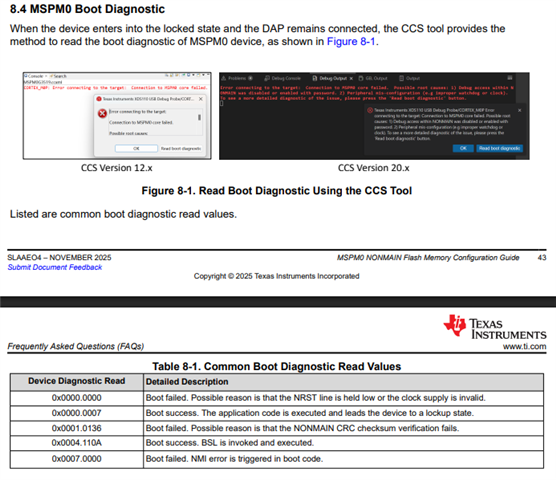
    I suggest you check the boot diagnostic read back value to determine what happens on the NONMAIN memory:

    You can refer to below documents to see the read back table:MSPM0 NONMAIN Flash Memory Configuration Guide

    Note that if read back as 0x0000.0036 which represents the NONMAIN is empty and are permanently locked. 

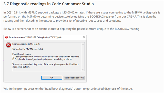
    Refer to below for read diagnostic instructions: https://dev.ti.com/tirex/explore/node?isTheia=false&node=A__ANk2FOM4WUAtKZQLHOjtNw__MSPM0-SDK__a3PaaoK__LATEST&placeholder=true 

    Below is the support packge link:

     [FAQ] MSPM0-SDK: MSPM0 Support Package Release for CCS 12.8.1  

    (CCS 20 directly support it)

    B.R.

    Sal

  • Hello Sal,

    CCS won't let me Read boot diagnostic as it only shows Force reset option when i try to connect even when i press it multiple times only this option appears as the DAP cannot connect anymore.

    This is the error that appears when i try to connect through CCS:

    And this is the error that appears when i try to test the connection through the target configurations:

  • Hello Sal,

    I just want to clarify the steps i made that may have locked the ECU:

    1. I Executed Factory reset using Uniflash tool to start with the default configurations

    2. I enabled the debug access feature in BCR [bcr.debugAccess = BCR_CFG_DEBUG_ACCESS_EN_PW] for the secure debug feature]

    3. I then enabled CSC IN BCR [bcr.CSCexist = BCR_CFG_CSC_EXISTS_EN]

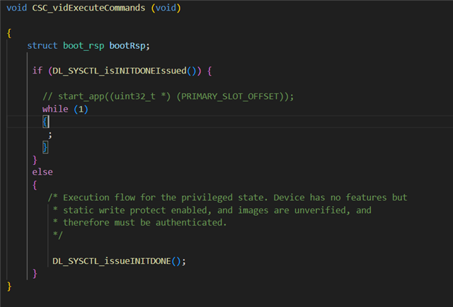
    4. I then Executed the following code just to ensure the INIT Done setting sequence:

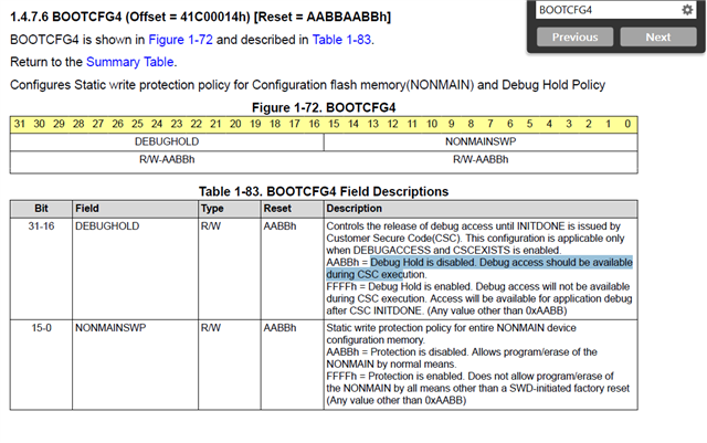
    My analysis is that by some reason the debug hold register is enabled where the debug is held during CSC execution and my code snippet stays in CSC so the debug is not released :

    Could you provide your feedback if this could be the root cause and if so what could possibly set the DebugHold register to 0xFFFF without explicitly setting it? can the factory reset set it to 0xFFFF value?

    Thank you,

  • Hi Mohamed,

    When CSC is enabled, the BSL entry is automatically forbidden. So, press S1 does not help.

    To test if the SWD connection well, you can keep NRST low and try to connect the device, then the boot diagnotsic read back value should be 0x0000.0000.

    In the meantime, I'll take a look what happens to SWD connection if force the MCU in the CSC state and enable debug hold feature.

    can the factory reset set it to 0xFFFF value?

    Factory reset set it to 0xAABB.

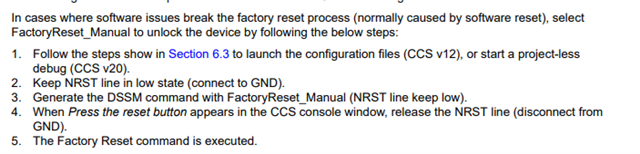
    And can you try below steps mentioned in the UG:

    B.R.

    Sal

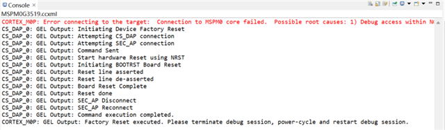
  • Hello Sal,

    I have tried the sequence you mentioned but i got this error when i released the NRST pin after the "press the reset button" message appeared 

  • Hi Mohamed,

    It looks weird. How about this read diagnostic value:

    To test if the SWD connection well, you can keep NRST low and try to connect the device, then the boot diagnotsic read back value should be 0x0000.0000.

    I'll take a test tomorrow on this: 

    I'll take a look what happens to SWD connection if force the MCU in the CSC state and enable debug hold feature.

    B.R.

    Sal

  • Hi Sal,

    Yes the diagnostic read is set to 0x000 while holding the NRST Low

  • Hi Mohamed,

    Yes the diagnostic read is set to 0x000 while holding the NRST Low

    Okay, this confirm there is no hardware issues in SWD interface.

    In the meantime, I'll take a look what happens to SWD connection if force the MCU in the CSC state and enable debug hold feature.

    I create a simple example to test debug hold feature:

        SYSCFG_DL_init();
    
        /* issue initdone */
        if(!DL_SYSCTL_isINITDONEIssued())
        {
            delay_cycles(80000000*10);  /* wait for 10s */
            /* End of Customer Secure Code */
            DL_SYSCTL_issueINITDONE();
        }

    Then I find connection failed but diagnostic read can work to verify the boot check pass.

    Additionally, the factory reset works when MCU keep in the CSC stage:

    So, I think it not the debug hold feature's impact.

    This is the error that appears when i try to connect through CCS:

    I see there reports the DAP error, according to the UG description:

    I see you mentioned you test the LaunchPad, so I assume there is no external NRST signal breaks connection.

    -> Please check VDD, Vcore, and NRST line to make sure everything is fine.

    Below is my suggestion to further debug the issues:

    Have you disabled SWD interface in NVM? disable SWD interface will results in no DAP connection including the diagnostic read.

    Is there any software reset exists? Like, IWDT, or software POR/BOOTRST. -> This might break the SWD connection and results in DAP error.

    Is the board functional now? I believe there might have some software behavior, if you reset the MCU, can you observe any signal in IO to prove the MCU works?

    B.R.

    Sal

  • Hi Sal,

    I have checked the connection and they are connected fine

     Also regarding The SWD Disabling , i did not explicitly disabled it , and  I do not believe there is an intentional software reset (IWDT or POR) in the application code.

    However , i updated the non main region to enable the CSC so i could tell all the steps i have done from scratch for you to see if something has crashed the ECU:

     CSC Enabling in non main the sequence i followed:

    At first i executed factory reset to start with default configuration of the BCR

    1. Read the non main area

    2. Updated BCR with CSCEXIST [bcr.CSCexist = BCR_CFG_CSC_EXISTS_EN]

    3. Calculated CRC on update BCR

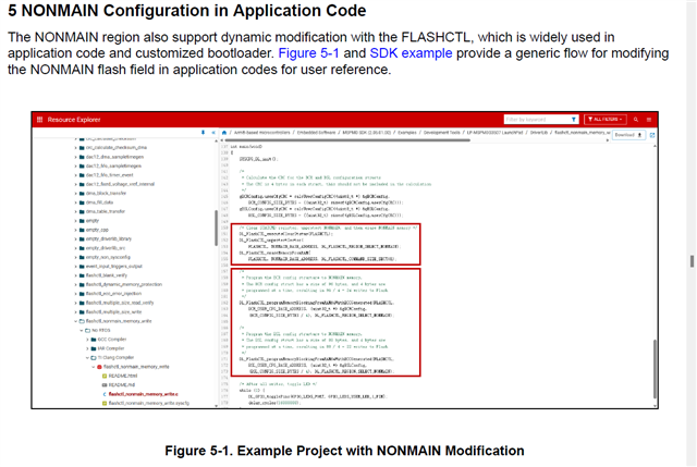
    4. Then Write the non main by unprotecting , erasing then write the sector following the "MSPM0 NONMAIN Flash Memory Configuration Guide" document steps:

    5. I then executed the code snippet i have mentioned before:

    So can you give your opinion about what might have happened that bricked the ECU?

    Thank you

  • Hi Mohamed,

    4. Then Write the non main by unprotecting , erasing then write the sector following the "MSPM0 NONMAIN Flash Memory Configuration Guide" document steps:

    The flow looks correct, the only concerning might be the CRC calculation wrong, or during the NONMAIN program, then device is somehow reset (maybe power is not stable), and results in the NONMAIN data broken.

    But the diagnostic read back should work at this scenario. Let me discuss internally on this part.

    -> Can you help share a example project for my debug?

    In the meantime, I have a suggestion for your temporary usage with below flow:

    1. Use Sysconfig to set the NVM property

    2. Compiler project with preset NVM property

    3. Download application & nonmain hex file into device (recommend select flash erase property: erase main and nonmain necessary sectors only)

    4. reset device to make the nonmain configuration take effect

    5. start debug.

    -> This works in my side when I test CSC debug hold feature.

    B.R.

    Sal