This thread has been locked.

If you have a related question, please click the "Ask a related question" button in the top right corner. The newly created question will be automatically linked to this question.

AM6442: AM64x: Understanding EHRPWM_SOCA vs physical pin output and 40 MHz requirement on custom board.

Part Number: AM6442
Other Parts Discussed in Thread: AM625

Hi TI Team,

I am working on an AM64x-based custom board using RT- Linux SDK, and I have a question regarding ePWM configuration, pin availability, and EHRPWM_SOCA usage.

In the SoC-level DTSI (main dtsi), I see that ePWM instances EPWM0 to EPWM8 are defined and enabled. When I tested the same software on the TI EVM board, I was able to configure and run the ePWM modules successfully.

However, on my custom board, only a limited number of pins are routed out, and no EPWM0 to EPWM8 pins are physically available.

My requirement is as follows:

  • I need to use EHRPWM_SOCA.
  • The signal frequency requirement is ~40 MHz
  • I initially expected to drive this as a pin signal, similar to EPWM outputs

custom board pins:
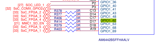
image.png

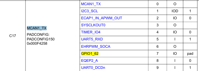
TRM AM64x Sitara™ Processors :

image.png


Can we use EHRPWM_SOCA to drive a 40 MHz external signal?

Thanks & Regards,
Ravilla Dinesh.


  • Hi Ravilla,

    • I need to use EHRPWM_SOCA.

    Is this a must?

    Please check if you can use SYSCLKOUT0 on the same pin (Mux 3), which will output a clean PLL derived clock.

    Regards,
    Vinu

  • Hi team,

    Please check if you can use SYSCLKOUT0 on the same pin (Mux 3), which will output a clean PLL derived clock.

    Based on your inputs changed the pin configurations.


    pin configuration:
    main_ehrpwm_soca_pins_default: main-ehrpwm-soca-pins-default {
          pinctrl-single,pins = <
              AM64X_IOPAD(0x0058, PIN_OUTPUT, 3) /* C17, Mode 3: EHRPWM_SOCA */
            >;
        };

    peripheral configuration:

    &epwm0 {
        pinctrl-names = "default";
        pinctrl-0 = <&main_ehrpwm_soca_pins_default>;  /* main_epwm0_pins_default */
        status = "okay";
    };

    kernel side:
    root@am64xx-evm:~# echo 0 > /sys/class/pwm/pwmchip1/export
    root@am64xx-evm:~# echo 50 > /sys/class/pwm/pwmchip1/pwm0/period
    root@am64xx-evm:~# echo 25 > /sys/class/pwm/pwmchip1/pwm0/duty_cycle
    root@am64xx-evm:~# echo 1 > /sys/class/pwm/pwmchip1/pwm0/enable

    But pin is not driving with 40MHZ.

    Thanks & Regards,
    Ravilla Dinesh.

  • Hi Ravilla,

    SYSCLKOUT0 is not an ePWM pin.

    As mentioned, please configure it with a PLL derived clock.

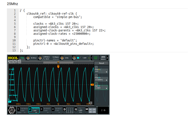
    Please refer  AM625: 50MHz output from CLKOUT0 for a similar issue.

    Regards,
    Vinu 

  • Hi Vinu,

    I am working on the AM64x (AM642 EVM) using Processor SDK Linux RT 09.02.

    I am trying to configure SYSCLKOUT0 (observed as clk:119 in clk_summary).


    Pinmux configuration:
    clkout0_pins_default: clkout0-default-pins {
                pinctrl-single,pins = <
                    AM64X_IOPAD(0x0258, PIN_OUTPUT, 3) /* (C17) SYSCLKOUT0 */
                >;
          };

    / {
        clkout0_ref: clkout0-ref-clk {
            compatible = "simple-pm-bus";      /* ← KEY FIX from TI E2E */
            #address-cells = <1>;
            #size-cells = <1>;
            ranges;

            assigned-clocks        = <&k3_clks 119 0>;
            assigned-clock-parents = <&k3_clks 119 1>;
            assigned-clock-rates   = <40000000>;

            pinctrl-names = "default";
            pinctrl-0     = <&clkout0_pins_default>;
        };
    };

    Clock summary output:
    root@am64xx-evm:~# cat /sys/kernel/debug/clk/clk_summary | grep "clk:119"
     clk:119:1                            0        0        0           0          0     0  50000         Y
     clk:119:0                            0        0        0           0          0     0  50000         Y

    Thanks & Regards,
    Ravilla Dinesh.

  • Hi Ravilla,

    I assume you are still not getting the required frequency.

    Can you please let me know how did you arrive on the device 119?

    After looking into this in deep, it will be difficult to generate 40Mhz using SYSCLKOUT0. You can generate either 50Mhz or 25Mhz with it.

    SYSCLKOUT0 not very flexible, if you need to generate 40 Mhz, you'll have to reprogram MAIN_0 PLL HSDIV4 Divider, which is unlikely, as it will affect the other peripherals which are using it.

    And you'll have to use either one of the following parent clock.

    • 123 (DEV_BOARD0_CLKOUT0_IN): The input muxed clock.
    • 124 (_PARENT_HSDIV4_16FFT_MAIN_0_HSDIVOUT4_CLK5): Parent option 1.
    • 125 (_PARENT_HSDIV4_16FFT_MAIN_0_HSDIVOUT4_CLK10): Parent option 2.

    The best option to generate 40Mhz is using the ePWM itself, if you have access to any one of the 18 configurable ePWM pins.

    Your next best bet will be to use TIMER_IO4 on C17. But since the internal functional clock is 250Mhz, there is no integer divisor which can perfectly yield 80Mhz (timer needs to toggle at 80Mhz: one for rising edge and one for falling edge)

    Also, unlike CLKOUT0 (which outputs a clock as soon as the clock framework enables it), a DMTimer must be explicitly started by software. For more information, refer: https://software-dl.ti.com/processor-sdk-linux/esd/AM64X/latest/exports/docs/linux/Foundational_Components/Kernel/Kernel_Drivers/DM-Timer.html

    Regards,
    Vinu

  • Hi Vinu,

    And you'll have to use either one of the following parent clock.

    [123 (DEV_BOARD0_CLKOUT0_IN): The input muxed clock.]

    • 124 (_PARENT_HSDIV4_16FFT_MAIN_0_HSDIVOUT4_CLK5): Parent option 1.
    • 125 (_PARENT_HSDIV4_16FFT_MAIN_0_HSDIVOUT4_CLK10): Parent option 2.

    Give some example configuration for reference for am6442(k3-am642-evm.dts).

    Thanks & Regards,

    Ravilla Dinesh.

  • Hi Ravilla,

    Give some example configuration for reference for am6442(k3-am642-evm.dts).

    Please refer the AM625 thread that I've shared earlier, just change the parent clock and pin control. (AM625: 50MHz output from CLKOUT0 )

    But keep in mind that you could get either 50Mhz or 25Mhz, not 40Mhz.

    Regards,
    Vinu

  • Hi Vinu,

    Based on your inputs.

    pin configuration:

    clkout0_pins_default: clkout0-default-pins {
                pinctrl-single,pins = <
                    AM64X_IOPAD(0x0258, PIN_OUTPUT, 3) /* (C17) SYSCLKOUT0 */
                >;
          };


    / {
        clkout0_ref: clkout0-ref-clk {
            compatible    = "simple-pm-bus";
            #clock-cells  = <0>;

            clocks                 = <&k3_clks 123 0>;
            assigned-clocks        = <&k3_clks 123 0>;
            assigned-clock-parents = <&k3_clks 125 2>;  
            assigned-clock-rates   = <25000000>;

            pinctrl-names = "default";
            pinctrl-0     = <&clkout0_pins_default>;
        };
    };

    root@am64xx-evm:~# cat /sys/kernel/debug/clk/clk_summary | grep -E "clk:12[0-5]"
     clk:125:4                            0        0        0       32552          0     0  50000         Y
     clk:125:3                            0        0        0    12500000          0     0  50000         Y
     clk:125:2                            0        0        0       29761          0     0  50000         Y
        clk:125:0                         0        0        0       29761          0     0  50000         Y
     clk:125:1                            0        0        0    25000000          0     0  50000         Y
     clk:123:0                            0        0        0    25000000          0     0  50000         Y


    Changing assigned-clock-rates from 25 MHz → 50 MHz reflects correctly in /sys/kernel/debug/clk/clk_summary.


    / {
        clkout0_ref: clkout0-ref-clk {
            compatible    = "simple-pm-bus";
            #clock-cells  = <0>;

            clocks                 = <&k3_clks 123 0>;
            assigned-clocks        = <&k3_clks 123 0>;
            assigned-clock-parents = <&k3_clks 125 2>;  
            assigned-clock-rates   = <50000000>;

            pinctrl-names = "default";
            pinctrl-0     = <&clkout0_pins_default>;
        };
    };

    root@am64xx-evm:~# cat /sys/kernel/debug/clk/clk_summary | grep -E "clk:12[0-5]"
     clk:125:4                            0        0        0       32552          0     0  50000         Y
     clk:125:3                            0        0        0    12500000          0     0  50000         Y
     clk:125:2                            0        0        0       29761          0     0  50000         Y
        clk:125:0                         0        0        0       29761          0     0  50000         Y
     clk:125:1                            0        0        0    25000000          0     0  50000         Y
     clk:123:0                            0        0        0    50000000          0     0  50000         Y

    Additional Observations:

    • But physical output remains fixed at ~125 MHz
    • Parent clock used: clk:125:2

    Issue:

    However, when probing the SYSCLKOUT0 (C17) pin using an oscilloscope, I consistently observe 125 MHz output, not 50 MHz.


    Thanks & Regards,
    Ravilla Dinesh


  • Hi Ravilla,

    Can you share your complete decompiled DTS and clock summary?

    Regards,
    Vinu

  • Hi Ravilla,

    Your DT nodes are malformed.

    Refer AM64X Clock Identifiers: https://software-dl.ti.com/tisci/esd/latest/5_soc_doc/am64x/clocks.html

            clocks                 = <&k3_clks 123 0>;

    This is a misunderstanding of how the k3_clks binding works.
    The correct format for referencing a TI SCI clock is <&k3_clks DEVICE_ID CLOCK_ID>.

    For AM64X, CLKOUT0 belongs to device 157(BOARD0), not device 123.

    Please try the following DT nodes

    clkout0_pins_default: clkout0-default-pins {
                pinctrl-single,pins = <
                    AM64X_IOPAD(0x0258, PIN_OUTPUT, 3) /* (C17) SYSCLKOUT0 */
                >;
          };
    
    
    / {
        clkout0_ref: clkout0-ref-clk {
            compatible    = "simple-pm-bus";
            #clock-cells  = <0>;
            
             /* 
             * Device 157 = BOARD_0
             * Clock 123  = CLKOUT0 Mux
             * Clock 125  = 25 MHz Parent from MAIN_0 PLL
             */
            
            assigned-clocks        = <&k3_clks 157 123>;
            assigned-clock-parents = <&k3_clks 157 125>;  
    
            pinctrl-names = "default";
            pinctrl-0     = <&clkout0_pins_default>;
        };
    };

    Regards,
    Vinu

  • Hi Vinu,

    Based on your inputs.

    124 (_PARENT_HSDIV4_16FFT_MAIN_0_HSDIVOUT4_CLK5).

    clkout0_pins_default: clkout0-default-pins {
                pinctrl-single,pins = <
                      AM64X_IOPAD(0x0258, PIN_OUTPUT, 3) /* (C17) SYSCLKOUT0 */
                >;
          };

    / {
        clkout0_ref: clkout0-ref-clk {
            compatible    = "simple-bus";      /* was simple-pm-bus — fixes probe */
            #address-cells = <1>;              /* required by simple-bus */
            #size-cells    = <1>;              /* required by simple-bus */
            ranges;

            /*
             * Device 157 = BOARD0
             * Clock 123  = DEV_BOARD0_CLKOUT0_IN (mux)
             * Clock 124  = HSDIV4_16FFT_MAIN_0_HSDIVOUT4_CLK5  -> 50 MHz
             * Clock 125  = HSDIV4_16FFT_MAIN_0_HSDIVOUT4_CLK10 -> 25 MHz
             */
            assigned-clocks        = <&k3_clks 157 123>;
            assigned-clock-parents = <&k3_clks 157 124>;   /* 50 MHz */

            pinctrl-names = "default";
            pinctrl-0     = <&clkout0_pins_default>;
        };
    };

    root@am64xx-evm:~# cat /sys/kernel/debug/pinctrl/*/pins 2>/dev/null | grep "0258"
    pin 150 (PIN150) 0:? a40258 00000000 pinctrl-single 
    root@am64xx-evm:~# cat /sys/kernel/debug/clk/clk_summary | grep "157"
     clk:157:125                          0        0        0    25000000          0     0  50000         Y
     clk:157:124                          0        0        0    50000000          0     0  50000         Y
        clk:157:123                       0        0        0    50000000          0     0  50000         Y

    125 (_PARENT_HSDIV4_16FFT_MAIN_0_HSDIVOUT4_CLK10)

    &main_pmx0 {
        clkout0_pins_default: clkout0-default-pins {
            pinctrl-single,pins = <
                AM64X_IOPAD(0x0258, PIN_OUTPUT, 3) /* (C17) SYSCLKOUT0 */
            >;
        };
    };

    / {
        clkout0_ref: clkout0-ref-clk {
            compatible    = "simple-pm-bus";
            #clock-cells  = <0>;
            
             /* 
             * Device 157 = BOARD_0
             * Clock 123  = CLKOUT0 Mux
             * Clock 125  = 25 MHz Parent from MAIN_0 PLL
             */
            
            assigned-clocks        = <&k3_clks 157 123>;
            assigned-clock-parents = <&k3_clks 157 125>;  

            pinctrl-names = "default";
            pinctrl-0     = <&clkout0_pins_default>;
        };
    };

    root@am64xx-evm:~# cat /sys/kernel/debug/pinctrl/*/pins 2>/dev/null | grep "0258"
    pin 150 (PIN150) 0:? a40258 00000000 pinctrl-single 
    root@am64xx-evm:~# cat /sys/kernel/debug/clk/clk_summary | grep "157"
     clk:157:125                          0        0        0    25000000          0     0  50000         Y
        clk:157:123                       0        0        0    25000000          0     0  50000         Y
     clk:157:124                          0        0        0    50000000          0     0  50000         Y


    Issue:

    However, when probing the SYSCLKOUT0 (C17) pin using an oscilloscope, I consistently observe 125 MHz output, not 50 MHz.


    Thanks & Regards,
    Ravilla Dinesh.


  • Hi Ravilla,

    The waveform does't look like a proper 125 Mhz signal. It looks more like a noise.

    Looking at your clock summary, the clocks are not enabled. 

    root@am64xx-evm:~# cat /sys/kernel/debug/clk/clk_summary | grep "157"
     clk:157:125                          0        0        0    25000000          0     0  50000         Y
     clk:157:124                          0        0        0    50000000          0     0  50000         Y
        clk:157:123                       0        0        0    50000000          0     0  50000         Y

    Why is the compatible simple-pm-bus was replaced with simple-bus?

    Also, with simple-pm-bus, the clocks property is needed to to enable it.

    I'm sharing a corrected DT node with the missing clocks param to enable the clock

    clkout0_pins_default: clkout0-default-pins {
                pinctrl-single,pins = <
                    AM64X_IOPAD(0x0258, PIN_OUTPUT, 3) /* (C17) SYSCLKOUT0 */
                >;
          };
    
    
    / {
        clkout0_ref: clkout0-ref-clk {
            compatible    = "simple-pm-bus";
            #clock-cells  = <0>;
            
             /* 
             * Device 157 = BOARD_0
             * Clock 123  = CLKOUT0 Mux
             * Clock 125  = 25 MHz Parent from MAIN_0 PLL
             */
             
            /* To enable clock on probe */
            clocks = <&k3_clks 157 123>;
            
            /* To configures the mux parent */
            assigned-clocks        = <&k3_clks 157 123>;
            assigned-clock-parents = <&k3_clks 157 125>;  /* 25 Mhz */
    
            pinctrl-names = "default";
            pinctrl-0     = <&clkout0_pins_default>;
        };
    };

    If it's still not enabled, you could try force-enabling it via debugfs for verifying.

    # Force-enable
    echo 1 > /sys/kernel/debug/clk/clk:157:123/clk_enable_count
    
    # Verify
    cat /sys/kernel/debug/clk/clk_summary | grep "157:123"

    Regards,
    Vinu

  • Hi Vinu,

    Based on your inputs.

    clkout0_pins_default: clkout0-default-pins {
                pinctrl-single,pins = <
                    AM64X_IOPAD(0x0258, PIN_OUTPUT, 3) /* (C17) SYSCLKOUT0 */
                >;
          };

    / {
        clkout0_ref: clkout0-ref-clk {
            compatible    = "simple-pm-bus";
            #clock-cells  = <0>;
            
             /* 
             * Device 157 = BOARD_0
             * Clock 123  = CLKOUT0 Mux
             * Clock 125  = 25 MHz Parent from MAIN_0 PLL
             */
             
            /* To enable clock on probe */
            clocks = <&k3_clks 157 123>;
            
            /* To configures the mux parent */
            assigned-clocks        = <&k3_clks 157 123>;
            assigned-clock-parents = <&k3_clks 157 125>;  /* 25 Mhz */

            pinctrl-names = "default";
            pinctrl-0     = <&clkout0_pins_default>;
        };
    };

    Output:
    root@am64xx-evm:~# cat /sys/kernel/debug/clk/clk_summary | grep "157"
     clk:157:125                          0        0        0    25000000          0     0  50000         Y
        clk:157:123                       0        0        0    25000000          0     0  50000         Y
     clk:157:124                          0        0        0    50000000          0     0  50000         Y
    root@am64xx-evm:~# cat /sys/kernel/debug/clk/clk_summary | grep "157:123"
        clk:157:123                       0        0        0    25000000          0     0  50000         Y
    root@am64xx-evm:~# echo 1 > /sys/kernel/debug/clk/clk:157:123/clk_enable_count
    -sh: echo: write error: Permission denied

    However, when probing the SYSCLKOUT0 (C17) pin using an oscilloscope, I consistently observe 125 MHz output, not 25 MHz.

    Thanks & regards,
    Ravilla Dinesh.

  • Hi Ravillla,

    Looks like the clock is again getting disabled, unlike AM62x.

    I'll try out this from my end, and get back to you by the end of this week.

    Regards,
    Vinu

  • Hi Ravilla,

    I have written a simple clock driver to stop the clock from getting disabled.

    I had to patch the DT as the CLOCKOUT0 (C17) pin is conflicting with MCAN1. Also the compatible string is changed.

    DT patch

    diff --git a/board-support/ti-linux-kernel-6.18.13+git-ti-rt/arch/arm64/boot/dts/ti/k3-am642-evm.dts b/board-support/ti-linux-kernel-6.18.13+git-ti-rt/arch/arm64/boot/dts/ti/k3-am642-evm.dts
    index 1267ab0f7..68b5bd3e5 100644
    --- a/board-support/ti-linux-kernel-6.18.13+git-ti-rt/arch/arm64/boot/dts/ti/k3-am642-evm.dts
    +++ b/board-support/ti-linux-kernel-6.18.13+git-ti-rt/arch/arm64/boot/dts/ti/k3-am642-evm.dts
    @@ -248,9 +248,38 @@ icssg1_emac1: port@1 {
     			};
     		};
     	};
    +
    +	 clkout0_ref: clkout0-ref-clk {
    +        compatible    = "custom,clkout0-enabler";
    +        
    +         /* 
    +         * Device 157 = BOARD_0
    +         * Clock 123  = CLKOUT0 Mux
    +         * Clock 125  = 25 MHz Parent from MAIN_0 PLL
    +         */
    +         
    +        /* To enable clock on probe */
    +        clocks = <&k3_clks 157 123>;
    +        
    +        /* To configures the mux parent */
    +        assigned-clocks        = <&k3_clks 157 123>;
    +        assigned-clock-parents = <&k3_clks 157 125>;  /* 25 Mhz */
    +
    +        pinctrl-names = "default";
    +        pinctrl-0     = <&clkout0_pins_default>;
    +    };
    +
    +
     };
     
     &main_pmx0 {
    +
    +	clkout0_pins_default: clkout0-default-pins {
    +        pinctrl-single,pins = <
    +            AM64X_IOPAD(0x0258, PIN_OUTPUT_PULLUP, 3) /* (C17) SYSCLKOUT0 */
    +        >;
    +    };
    +
     	main_mmc1_pins_default: main-mmc1-default-pins {
     		pinctrl-single,pins = <
     			AM64X_IOPAD(0x0294, PIN_INPUT_PULLUP, 0) /* (J19) MMC1_CMD */
    @@ -389,13 +418,6 @@ AM64X_IOPAD(0x0250, PIN_OUTPUT, 0) /* (A17) MCAN0_TX */
     		>;
     	};
     
    -	main_mcan1_pins_default: main-mcan1-default-pins {
    -		pinctrl-single,pins = <
    -			AM64X_IOPAD(0x025c, PIN_INPUT, 0) /* (D17) MCAN1_RX */
    -			AM64X_IOPAD(0x0258, PIN_OUTPUT, 0) /* (C17) MCAN1_TX */
    -		>;
    -	};
    -
     	ddr_vtt_pins_default: ddr-vtt-default-pins {
     		bootph-all;
     		pinctrl-single,pins = <
    @@ -723,10 +745,7 @@ &main_mcan0 {
     };
     
     &main_mcan1 {
    -	status = "okay";
    -	pinctrl-names = "default";
    -	pinctrl-0 = <&main_mcan1_pins_default>;
    -	phys = <&transceiver2>;
    +	status = "disabled";
     };
     
     &icssg1_mdio {

    simple_clock_enabler.c

    #include <linux/module.h>
    #include <linux/platform_device.h>
    #include <linux/clk.h>
    #include <linux/of.h>
    #include <linux/of_device.h>
    
    struct clkout0_priv {
        struct clk *clk;
    };
    
    static int clkout0_probe(struct platform_device *pdev)
    {
        struct clkout0_priv *priv;
        int ret;
    
        priv = devm_kzalloc(&pdev->dev, sizeof(*priv), GFP_KERNEL);
        if (!priv)
            return -ENOMEM;
    
        priv->clk = devm_clk_get(&pdev->dev, NULL);
        if (IS_ERR(priv->clk)) {
            dev_err(&pdev->dev, "Failed to get clock\n");
            return PTR_ERR(priv->clk);
        }
    
        ret = clk_prepare_enable(priv->clk);
        if (ret) {
            dev_err(&pdev->dev, "Failed to enable clock\n");
            return ret;
        }
    
        platform_set_drvdata(pdev, priv);
        dev_info(&pdev->dev, "CLKOUT0 successfully enabled!\n");
    
        return 0;
    }
    
    static void clkout0_remove(struct platform_device *pdev)
    {
        struct clkout0_priv *priv = platform_get_drvdata(pdev);
        clk_disable_unprepare(priv->clk);
    }
    
    static const struct of_device_id clkout0_of_match[] = {
        { .compatible = "custom,clkout0-enabler", },
        { }
    };
    MODULE_DEVICE_TABLE(of, clkout0_of_match);
    
    static struct platform_driver clkout0_driver = {
        .probe = clkout0_probe,
        .remove = clkout0_remove,
        .driver = {
            .name = "clkout0-enabler",
            .of_match_table = clkout0_of_match,
        },
    };
    
    module_platform_driver(clkout0_driver);
    
    MODULE_AUTHOR("TI");
    MODULE_DESCRIPTION("Simple clock enable driver for AM64x CLKOUT0");
    MODULE_LICENSE("GPL");
    MODULE_VERSION("0.01");

    Makefile

    obj-m := simple_clock_enabler.o
    
    SDK_INSTALL_DIR ?= $(HOME)/ti-processor-sdk-linux-rt-am64xx-evm-12.00.00.07.04
    CROSS_COMPILE_64 ?= $(SDK_INSTALL_DIR)/linux-devkit/sysroots/x86_64-arago-linux/usr/bin/aarch64-oe-linux/aarch64-oe-linux-
    KERNEL_SRC ?= $(SDK_INSTALL_DIR)/board-support/ti-linux-kernel-6.18.13+git-ti-rt
    
    PWD := $(shell pwd)
    
    all:
    	$(MAKE) -C $(KERNEL_SRC) M=$(PWD) ARCH=arm64 CROSS_COMPILE=$(CROSS_COMPILE_64) modules
    
    clean:
    	$(MAKE) -C $(KERNEL_SRC) M=$(PWD) clean
    

    You will have to export the SDK_INSTALL_DIR before building the kernel module.

    The clock will be enabled after inserting the module.

    Logs with before and after clock summary

    root@am64xx-evm:~# cat /sys/kernel/debug/clk/clk_summary | grep 157
     clk:157:125                         0       0        0        25000000    0          0     50000      Y   deviceless                      no_connection_id         
     clk:157:124                         0       0        0        50000000    0          0     50000      Y   deviceless                      no_connection_id         
        clk:157:123                      0       0        0        50000000    0          0     50000      Y      deviceless                      no_connection_id         
    root@am64xx-evm:~# insmod ../home/simple_clock_enabler.ko 
    [   68.213229] simple_clock_enabler: loading out-of-tree module taints kernel.
    [   68.215600] clkout0-enabler clkout0-ref-clk: CLKOUT0 successfully enabled!
    root@am64xx-evm:~# cat /sys/kernel/debug/clk/clk_summary | grep 157
     clk:157:125                         1       1        0        25000000    0          0     50000      Y   deviceless                      no_connection_id         
        clk:157:123                      1       1        0        25000000    0          0     50000      Y      clkout0-ref-clk                 no_connection_id         
     clk:157:124                         0       0        0        50000000    0          0     50000      Y   deviceless                      no_connection_id         
    root@am64xx-evm:~# 

    I couldn't probe the pin. Please try this out from your end.

    Regards,
    Vinu

  • Hi Vinu,

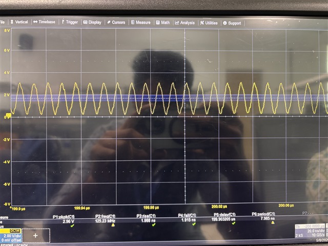
    Based on your inputs, I enabled the clock. During probing, the pin was driving at 125 MHz.

    root@am64xx-evm:~# cat /sys/kernel/debug/clk/clk_summary | grep 157
    clk:157:125 0 0 0 25000000 0 0 50000 Y
    clk:157:124 0 0 0 50000000 0 0 50000 Y
    clk:157:123 0 0 0 50000000 0 0 50000 Y
    root@am64xx-evm:~# insmod /home/root/simple_clock_enabler.ko
    [ 56.374130] clkout0-enabler clkout0-ref-clk: CLKOUT0 successfully enabled!
    root@am64xx-evm:~# cat /sys/kernel/debug/clk/clk_summary | grep 157
    clk:157:125 1 1 0 25000000 0 0 50000 Y
    clk:157:123 1 1 0 25000000 0 0 50000 Y
    clk:157:124 0 0 0 50000000 0 0 50000 Y

    Attaching the SS at the bottom for reference.


    Thanks & Regards,

    Ravilla Dinesh

  • Hi Ravilla,

    Can you try making the pin C17 a GPIO and see if you are able to toggle it? 

    This will help to verify the hardware connections.

    From the SW side, all that is needed is already done. And the clock summary is showing the correct frequency, with the clock enabled.

    I'll check if anything more is required on the SW side. But please make sure the hw connections are correct.

    Also, please make sure you don't have any conflict in the device tree. Share the decompiled DT if possible.

    Regards,
    Vinu

  • Hi Vinu,

    Can you try making the pin C17 a GPIO and see if you are able to toggle it? 

    Verified the pin functionality by configuring it as GPIO.
    GPIO toggle is working correctly and the pin is driving HIGH and LOW as expected.
    This confirms the pad configuration and hardware connection are fine.

    root@am64xx-evm:~# gpioset gpiochip1 62=0
    root@am64xx-evm:~# gpioset gpiochip1 62=1
    root@am64xx-evm:~# gpioset gpiochip1 62=0

    Thanks & Regards,
    Ravilla Dinesh.

  • Hi Ravilla,

    Thanks for confirming.

    Share the decompiled DT if possible.

    Also, please share the DT used for configuring the pin as GPIO.

    Regards,
    Vinu

  • Hi Vinu,

    Please find below the DT configurations used for both GPIO mode and SYSCLKOUT0 mode.

    Also, please share the DT used for configuring the pin as GPIO.

    GPIO toggle was verified successfully on the same pin, confirming that the pad configuration and hardware connection are functioning properly.
    GPIO configuration:

    // SPDX-License-Identifier: GPL-2.0
    /*
     * Copyright (C) 2020-2021 Texas Instruments Incorporated - https://www.ti.com/
     */
    
    /dts-v1/;
    
    #include <dt-bindings/phy/phy.h>
    #include <dt-bindings/mux/ti-serdes.h>
    #include <dt-bindings/leds/common.h>
    #include <dt-bindings/gpio/gpio.h>
    #include <dt-bindings/net/ti-dp83867.h>
    #include "k3-am642.dtsi"
    
    / {
    	compatible = "ti,am642-evm", "ti,am642";
    	model = "Texas Instruments AM642 EVM";
    
    	chosen {
    		stdout-path = "serial2:115200n8";
    		bootargs = "console=ttyS2,115200n8 earlycon=ns16550a,mmio32,0x02800000";
    		
    	};
    
    	aliases {
    		serial1 = &main_uart1; 
    		serial2 = &main_uart0;
    		serial3 = &main_uart4;
    		i2c0 = &main_i2c0;
    		i2c1 = &main_i2c1;
    		mmc0 = &sdhci0;
    		mmc1 = &sdhci1;
    		ethernet0 = &cpsw_port1;
    		ethernet1 = &cpsw_port2;
    		ethernet2 = &icssg1_emac0;
    		ethernet3 = &icssg1_emac1;
    	};
    
    	memory@80000000 {
    		bootph-all;
    		device_type = "memory";
    		/* 2G RAM */
    		reg = <0x00000000 0x80000000 0x00000000 0x80000000>;
    
    	};
    
    	reserved-memory {
    		#address-cells = <2>;
    		#size-cells = <2>;
    		ranges;
    
    		secure_ddr: optee@9e800000 {
    			reg = <0x00 0x9e800000 0x00 0x01800000>; /* for OP-TEE */
    			alignment = <0x1000>;
    			no-map;
    		};
    
    		main_r5fss0_core0_dma_memory_region: r5f-dma-memory@a0000000 {
    			compatible = "shared-dma-pool";
    			reg = <0x00 0xa0000000 0x00 0x100000>;
    			no-map;
    		};
    
    		main_r5fss0_core0_memory_region: r5f-memory@a0100000 {
    			compatible = "shared-dma-pool";
    			reg = <0x00 0xa0100000 0x00 0xf00000>;
    			no-map;
    		};
    
    		main_r5fss0_core1_dma_memory_region: r5f-dma-memory@a1000000 {
    			compatible = "shared-dma-pool";
    			reg = <0x00 0xa1000000 0x00 0x100000>;
    			no-map;
    		};
    
    		main_r5fss0_core1_memory_region: r5f-memory@a1100000 {
    			compatible = "shared-dma-pool";
    			reg = <0x00 0xa1100000 0x00 0xf00000>;
    			no-map;
    		};
    
    		main_r5fss1_core0_dma_memory_region: r5f-dma-memory@a2000000 {
    			compatible = "shared-dma-pool";
    			reg = <0x00 0xa2000000 0x00 0x100000>;
    			no-map;
    		};
    
    		main_r5fss1_core0_memory_region: r5f-memory@a2100000 {
    			compatible = "shared-dma-pool";
    			reg = <0x00 0xa2100000 0x00 0xf00000>;
    			no-map;
    		};
    
    		main_r5fss1_core1_dma_memory_region: r5f-dma-memory@a3000000 {
    			compatible = "shared-dma-pool";
    			reg = <0x00 0xa3000000 0x00 0x100000>;
    			no-map;
    		};
    
    		main_r5fss1_core1_memory_region: r5f-memory@a3100000 {
    			compatible = "shared-dma-pool";
    			reg = <0x00 0xa3100000 0x00 0xf00000>;
    			no-map;
    		};
    
    		mcu_m4fss_dma_memory_region: m4f-dma-memory@a4000000 {
    			compatible = "shared-dma-pool";
    			reg = <0x00 0xa4000000 0x00 0x100000>;
    			no-map;
    		};
    
    		mcu_m4fss_memory_region: m4f-memory@a4100000 {
    			compatible = "shared-dma-pool";
    			reg = <0x00 0xa4100000 0x00 0xf00000>;
    			no-map;
    		};
    
    	};
    
    	evm_12v0: fixedregulator-evm12v0 {
    		/* main DC jack */
    		compatible = "regulator-fixed";
    		regulator-name = "evm_12v0";
    		regulator-min-microvolt = <12000000>;
    		regulator-max-microvolt = <12000000>;
    		regulator-always-on;
    		regulator-boot-on;
    	};
    
    	vsys_5v0: fixedregulator-vsys5v0 {
    		/* output of LM5140 */
    		compatible = "regulator-fixed";
    		regulator-name = "vsys_5v0";
    		regulator-min-microvolt = <5000000>;
    		regulator-max-microvolt = <5000000>;
    		vin-supply = <&evm_12v0>;
    		regulator-always-on;
    		regulator-boot-on;
    	};
    
    	vsys_3v3: fixedregulator-vsys3v3 {
    		/* output of LM5140 */
    		compatible = "regulator-fixed";
    		regulator-name = "vsys_3v3";
    		regulator-min-microvolt = <3300000>;
    		regulator-max-microvolt = <3300000>;
    		vin-supply = <&evm_12v0>;
    		regulator-always-on;
    		regulator-boot-on;
    	};
    
    	vdd_mmc1: fixed-regulator-sd {
    		/* TPS2051BD */
    		compatible = "regulator-fixed";
    		regulator-name = "vdd_mmc1";
    		regulator-min-microvolt = <3300000>;
    		regulator-max-microvolt = <3300000>;
    		regulator-boot-on;
    		enable-active-high;
    		vin-supply = <&vsys_3v3>;
    		/*gpio = <&exp1 6 GPIO_ACTIVE_HIGH>;*/
    		pinctrl-names = "default";
       		pinctrl-0 = <&i2c_io_expander_pins_default>;
    		gpios = <&main_gpio1 63  GPIO_ACTIVE_HIGH>;
    	};
    
    	vddb: fixedregulator-vddb {
    		compatible = "regulator-fixed";
    		regulator-name = "vddb_3v3_display";
    		regulator-min-microvolt = <3300000>;
    		regulator-max-microvolt = <3300000>;
    		vin-supply = <&vsys_3v3>;
    		regulator-always-on;
    		regulator-boot-on;
    	};
    
    	leds {
    		compatible = "gpio-leds";
    
    		led-0 {
    			label = "am64-evm:red:heartbeat";
    			gpios = <&exp1 16 GPIO_ACTIVE_HIGH>;
    			linux,default-trigger = "heartbeat";
    			function = LED_FUNCTION_HEARTBEAT;
    			default-state = "off";
    		};
    	};
     
    	mdio_mux: mux-controller {
    		compatible = "gpio-mux";
    		#mux-control-cells = <0>;
    
    		mux-gpios = <&exp1 12 GPIO_ACTIVE_HIGH>;
    	};
    
    	mdio_mux_1: mdio-mux-1 {
    		compatible = "mdio-mux-multiplexer";
    		/*mux-controls = <&mdio_mux>;*/		/*removed*/
    		mdio-parent-bus = <&cpsw3g_mdio>;
    		#address-cells = <1>;
    		#size-cells = <0>;
    
    		mdio@1 {
    			reg = <0x1>;
    			#address-cells = <1>;
    			#size-cells = <0>;
    
    			cpsw3g_phy3: ethernet-phy@3 {
    				reg = <3>;
    				tx-internal-delay-ps = <250>;
    				rx-internal-delay-ps = <2000>;
    			};
    		};
    	};
    
    	transceiver1: can-phy0 {
    		compatible = "ti,tcan1042";
    		#phy-cells = <0>;
    		max-bitrate = <5000000>;
    		standby-gpios = <&exp1 8 GPIO_ACTIVE_HIGH>;
    	};
    
    	transceiver2: can-phy1 {
    		compatible = "ti,tcan1042";
    		#phy-cells = <0>;
    		max-bitrate = <5000000>;
    		standby-gpios = <&exp1 9 GPIO_ACTIVE_HIGH>;
    	};
    
    	icssg1_eth: icssg1-eth {
    		compatible = "ti,am642-icssg-prueth";
    		pinctrl-names = "default";
    		pinctrl-0 = <&icssg1_rgmii1_pins_default>;
    
    		sram = <&oc_sram>;
    		ti,prus = <&pru1_0>, <&rtu1_0>, <&tx_pru1_0>, <&pru1_1>, <&rtu1_1>, <&tx_pru1_1>;
    		firmware-name = "ti-pruss/am65x-sr2-pru0-prueth-fw.elf",
    				"ti-pruss/am65x-sr2-rtu0-prueth-fw.elf",
    				"ti-pruss/am65x-sr2-txpru0-prueth-fw.elf",
    				"ti-pruss/am65x-sr2-pru1-prueth-fw.elf",
    				"ti-pruss/am65x-sr2-rtu1-prueth-fw.elf",
    				"ti-pruss/am65x-sr2-txpru1-prueth-fw.elf";
    
    		ti,pruss-gp-mux-sel = <2>,	/* MII mode */
    				      <2>,
    				      <2>,
    				      <2>,	/* MII mode */
    				      <2>,
    				      <2>;
    
    		ti,mii-g-rt = <&icssg1_mii_g_rt>;
    		ti,mii-rt = <&icssg1_mii_rt>;
    		ti,pa-stats = <&icssg1_pa_stats>;
    		iep = <&icssg1_iep0>,  <&icssg1_iep1>;
    
    		interrupt-parent = <&icssg1_intc>;
    		interrupts = <24 0 2>, <25 1 3>;
    		interrupt-names = "tx_ts0", "tx_ts1";
    
    		dmas = <&main_pktdma 0xc200 15>, /* egress slice 0 */
    		       <&main_pktdma 0xc201 15>, /* egress slice 0 */
    		       <&main_pktdma 0xc202 15>, /* egress slice 0 */
    		       <&main_pktdma 0xc203 15>, /* egress slice 0 */
    		       <&main_pktdma 0xc204 15>, /* egress slice 1 */
    		       <&main_pktdma 0xc205 15>, /* egress slice 1 */
    		       <&main_pktdma 0xc206 15>, /* egress slice 1 */
    		       <&main_pktdma 0xc207 15>, /* egress slice 1 */
    		       <&main_pktdma 0x4200 15>, /* ingress slice 0 */
    		       <&main_pktdma 0x4201 15>, /* ingress slice 1 */
    		       <&main_pktdma 0x4202 0>, /* mgmnt rsp slice 0 */
    		       <&main_pktdma 0x4203 0>; /* mgmnt rsp slice 1 */
    		dma-names = "tx0-0", "tx0-1", "tx0-2", "tx0-3",
    			    "tx1-0", "tx1-1", "tx1-2", "tx1-3",
    			    "rx0", "rx1";
    
    		ethernet-ports {
    			#address-cells = <1>;
    			#size-cells = <0>;
    			icssg1_emac0: port@0 {
    				reg = <0>;
    				phy-handle = <&icssg1_phy1>;
    				phy-mode = "rgmii-id";
    				ti,syscon-rgmii-delay = <&main_conf 0x4110>;
    				/* Filled in by bootloader */
    				local-mac-address = [00 00 00 00 00 00];
    			};
    			icssg1_emac1: port@1 {
    				reg = <1>;
    				ti,syscon-rgmii-delay = <&main_conf 0x4114>;
    				/* Filled in by bootloader */
    				local-mac-address = [00 00 00 00 00 00];
    				status = "disabled";
    			};
    		};
    	};
    };
    
    &main_pmx0 {
    	main_mmc1_pins_default: main-mmc1-pins-default {
    		pinctrl-single,pins = <
    			AM64X_IOPAD(0x0294, PIN_INPUT_PULLUP, 0) /* (J19) MMC1_CMD */
    			AM64X_IOPAD(0x028c, PIN_INPUT_PULLDOWN, 0) /* (L20) MMC1_CLK */
    			AM64X_IOPAD(0x0288, PIN_INPUT_PULLUP, 0) /* (K21) MMC1_DAT0 */
    			AM64X_IOPAD(0x0284, PIN_INPUT_PULLUP, 0) /* (L21) MMC1_DAT1 */
    			AM64X_IOPAD(0x0280, PIN_INPUT_PULLUP, 0) /* (K19) MMC1_DAT2 */
    			AM64X_IOPAD(0x027c, PIN_INPUT_PULLUP, 0) /* (K18) MMC1_DAT3 */
    			AM64X_IOPAD(0x0298, PIN_INPUT_PULLUP, 0) /* (D19) MMC1_SDCD */
    			AM64X_IOPAD(0x029c, PIN_INPUT, 0) /* (C20) MMC1_SDWP */
    			AM64X_IOPAD(0x0290, PIN_INPUT, 0) /* MMC1_CLKLB */
    		>;
    	};
    
    	main_uart1_pins_default: main-uart1-default-pins {
    		bootph-all;
    		pinctrl-single,pins = <
    			/*AM64X_IOPAD(0x0248, PIN_INPUT, 0)*/		/* (D16) UART1_CTSn */
    			/*AM64X_IOPAD(0x024c, PIN_OUTPUT, 0)*/		/* (E16) UART1_RTSn */
    			AM64X_IOPAD(0x0240, PIN_INPUT, 0)		/* (E15) UART1_RXD */
    			AM64X_IOPAD(0x0244, PIN_OUTPUT, 0)		/* (E14) UART1_TXD */
    		>;
    	};
    
    	main_uart0_pins_default: main-uart0-default-pins {
    		bootph-all;
    		pinctrl-single,pins = <
    			/*AM64X_IOPAD(0x0238, PIN_INPUT, 0)*/ /* (B16) UART0_CTSn */
    			/*AM64X_IOPAD(0x023c, PIN_OUTPUT, 0)*/ /* (A16) UART0_RTSn */
    			AM64X_IOPAD(0x0230, PIN_INPUT, 0) /* (D15) UART0_RXD */
    			AM64X_IOPAD(0x0234, PIN_OUTPUT, 0) /* (C16) UART0_TXD */
    		>;
    	};


    	main_spi0_pins_default: main-spi0-pins-default {
    		pinctrl-single,pins = <
    			AM64X_IOPAD(0x0210, PIN_INPUT, 0) /* (D13) SPI0_CLK */
    			AM64X_IOPAD(0x0208, PIN_OUTPUT, 0) /* (D12) SPI0_CS0 */
    			AM64X_IOPAD(0x0214, PIN_OUTPUT, 0) /* (A13) SPI0_D0 */
    			AM64X_IOPAD(0x0218, PIN_INPUT, 0) /* (A14) SPI0_D1 */
    		>;
    	};


    	main_i2c0_pins_default: main-i2c0-default-pins {
    		bootph-all;
    		pinctrl-single,pins = <
    			AM64X_IOPAD(0x0260, PIN_INPUT_PULLUP, 0) /* (A18) I2C0_SCL */
    			AM64X_IOPAD(0x0264, PIN_INPUT_PULLUP, 0) /* (B18) I2C0_SDA */
    		>;
    	};
    	
    
    	main_i2c1_pins_default: main-i2c1-default-pins {
    		bootph-all;
    		pinctrl-single,pins = <
    			AM64X_IOPAD(0x0268, PIN_INPUT_PULLUP, 0) /* (C18) I2C1_SCL */
    			AM64X_IOPAD(0x026c, PIN_INPUT_PULLUP, 0) /* (B19) I2C1_SDA */
    		>;
    	};	


    	mdio1_pins_default: mdio1-pins-default {
    		pinctrl-single,pins = <
    			AM64X_IOPAD(0x01fc, PIN_OUTPUT, 4) /* (R2) PRG0_PRU1_GPO19.MDIO0_MDC */
    			AM64X_IOPAD(0x01f8, PIN_INPUT, 4) /* (P5) PRG0_PRU1_GPO18.MDIO0_MDIO */
    		>;
    	};
    
    	rgmii1_pins_default: rgmii1-pins-default {
    		pinctrl-single,pins = <
    			AM64X_IOPAD(0x01cc, PIN_INPUT, 4) /* (W5) PRG0_PRU1_GPO7.RGMII1_RD0 */
    			AM64X_IOPAD(0x01d4, PIN_INPUT, 4) /* (Y5) PRG0_PRU1_GPO9.RGMII1_RD1 */
    			AM64X_IOPAD(0x01d8, PIN_INPUT, 4) /* (V6) PRG0_PRU1_GPO10.RGMII1_RD2 */
    			AM64X_IOPAD(0x01f4, PIN_INPUT, 4) /* (V5) PRG0_PRU1_GPO17.RGMII1_RD3 */
    			AM64X_IOPAD(0x0188, PIN_INPUT, 4) /* (AA5) PRG0_PRU0_GPO10.RGMII1_RXC */
    			AM64X_IOPAD(0x0184, PIN_INPUT, 4) /* (W6) PRG0_PRU0_GPO9.RGMII1_RX_CTL */
    			AM64X_IOPAD(0x0124, PIN_OUTPUT, 4) /* (V15) PRG1_PRU1_GPO7.RGMII1_TD0 */
    			AM64X_IOPAD(0x012c, PIN_OUTPUT, 4) /* (V14) PRG1_PRU1_GPO9.RGMII1_TD1 */
    			AM64X_IOPAD(0x0130, PIN_OUTPUT, 4) /* (W14) PRG1_PRU1_GPO10.RGMII1_TD2 */
    			AM64X_IOPAD(0x014c, PIN_OUTPUT, 4) /* (AA14) PRG1_PRU1_GPO17.RGMII1_TD3 */
    			AM64X_IOPAD(0x00e0, PIN_OUTPUT, 4) /* (U14) PRG1_PRU0_GPO10.RGMII1_TXC */
    			AM64X_IOPAD(0x00dc, PIN_OUTPUT, 4) /* (U15) PRG1_PRU0_GPO9.RGMII1_TX_CTL */
    		>;
    	};
    
           rgmii2_pins_default: rgmii2-pins-default {
    		pinctrl-single,pins = <
    			AM64X_IOPAD(0x0108, PIN_INPUT, 4) /* (W11) PRG1_PRU1_GPO0.RGMII2_RD0 */
    			AM64X_IOPAD(0x010c, PIN_INPUT, 4) /* (V11) PRG1_PRU1_GPO1.RGMII2_RD1 */
    			AM64X_IOPAD(0x0110, PIN_INPUT, 4) /* (AA12) PRG1_PRU1_GPO2.RGMII2_RD2 */
    			AM64X_IOPAD(0x0114, PIN_INPUT, 4) /* (Y12) PRG1_PRU1_GPO3.RGMII2_RD3 */
    			AM64X_IOPAD(0x0120, PIN_INPUT, 4) /* (U11) PRG1_PRU1_GPO6.RGMII2_RXC */
    			AM64X_IOPAD(0x0118, PIN_INPUT, 4) /* (W12) PRG1_PRU1_GPO4.RGMII2_RX_CTL */
    			AM64X_IOPAD(0x0134, PIN_OUTPUT, 4) /* (AA10) PRG1_PRU1_GPO11.RGMII2_TD0 */
    			AM64X_IOPAD(0x0138, PIN_OUTPUT, 4) /* (V10) PRG1_PRU1_GPO12.RGMII2_TD1 */
    			AM64X_IOPAD(0x013c, PIN_OUTPUT, 4) /* (U10) PRG1_PRU1_GPO13.RGMII2_TD2 */
    			AM64X_IOPAD(0x0140, PIN_OUTPUT, 4) /* (AA11) PRG1_PRU1_GPO14.RGMII2_TD3 */
    			AM64X_IOPAD(0x0148, PIN_OUTPUT, 4) /* (Y10) PRG1_PRU1_GPO16.RGMII2_TXC */
    			AM64X_IOPAD(0x0144, PIN_OUTPUT, 4) /* (Y11) PRG1_PRU1_GPO15.RGMII2_TX_CTL */
    		>;
    	};
    
    	main_usb0_pins_default: main-usb0-pins-default {
    		bootph-all;
    		pinctrl-single,pins = <
    			AM64X_IOPAD(0x02a8, PIN_OUTPUT, 0) /* (E19) USB0_DRVVBUS */
    		>;
    	};
    
    	ospi0_pins_default: ospi0-pins-default {
    		pinctrl-single,pins = <
    			AM64X_IOPAD(0x0000, PIN_OUTPUT, 0) /* (N20) OSPI0_CLK */
    			AM64X_IOPAD(0x002c, PIN_OUTPUT, 0) /* (L19) OSPI0_CSn0 */
    			AM64X_IOPAD(0x000c, PIN_INPUT, 0) /* (M19) OSPI0_D0 */
    			AM64X_IOPAD(0x0010, PIN_INPUT, 0) /* (M18) OSPI0_D1 */
    			AM64X_IOPAD(0x0014, PIN_INPUT, 0) /* (M20) OSPI0_D2 */
    			AM64X_IOPAD(0x0018, PIN_INPUT, 0) /* (M21) OSPI0_D3 */
    			AM64X_IOPAD(0x001c, PIN_INPUT, 0) /* (P21) OSPI0_D4 */
    			AM64X_IOPAD(0x0020, PIN_INPUT, 0) /* (P20) OSPI0_D5 */
    			AM64X_IOPAD(0x0024, PIN_INPUT, 0) /* (N18) OSPI0_D6 */
    			AM64X_IOPAD(0x0028, PIN_INPUT, 0) /* (M17) OSPI0_D7 */
    			AM64X_IOPAD(0x0008, PIN_INPUT, 0) /* (N19) OSPI0_DQS */
    		>;
    	};
    
    	main_ecap0_pins_default: main-ecap0-pins-default {
    		pinctrl-single,pins = <
    			AM64X_IOPAD(0x0270, PIN_INPUT, 0) /* (D18) ECAP0_IN_APWM_OUT */
    		>;
    	};
    
    	main_mcan0_pins_default: main-mcan0-pins-default {
    		pinctrl-single,pins = <
    			AM64X_IOPAD(0x0254, PIN_INPUT, 0) 
    			AM64X_IOPAD(0x0250, PIN_OUTPUT, 0) 
    		>;
    	};
    
    	/*main_mcan1_pins_default: main-mcan1-pins-default {
    		pinctrl-single,pins = <
    			AM64X_IOPAD(0x025c, PIN_INPUT, 0) 
    			AM64X_IOPAD(0x0258, PIN_OUTPUT, 0)
    		>;
    	};*/
    
    	icssg1_mdio1_pins_default: icssg1-mdio1-pins-default {
    		pinctrl-single,pins = <
    			AM64X_IOPAD(0x015c, PIN_OUTPUT, 0) /* (Y6) PRG1_MDIO0_MDC */
    			AM64X_IOPAD(0x0158, PIN_INPUT, 0) /* (AA6) PRG1_MDIO0_MDIO */
    		>;
    	};
    
    	icssg1_rgmii1_pins_default: icssg1-rgmii1-pins-default {
    		pinctrl-single,pins = <
    			AM64X_IOPAD(0x00b8, PIN_INPUT, 2) /* (Y7) PRG1_PRU0_GPO0.PRG1_RGMII1_RD0 */
    			AM64X_IOPAD(0x00bc, PIN_INPUT, 2) /* (U8) PRG1_PRU0_GPO1.PRG1_RGMII1_RD1 */
    			AM64X_IOPAD(0x00c0, PIN_INPUT, 2) /* (W8) PRG1_PRU0_GPO2.PRG1_RGMII1_RD2 */
    			AM64X_IOPAD(0x00c4, PIN_INPUT, 2) /* (V8) PRG1_PRU0_GPO3.PRG1_RGMII1_RD3 */
    			AM64X_IOPAD(0x00d0, PIN_INPUT, 2) /* (AA7) PRG1_PRU0_GPO6.PRG1_RGMII1_RXC */
    			AM64X_IOPAD(0x00c8, PIN_INPUT, 2) /* (Y8) PRG1_PRU0_GPO4.PRG1_RGMII1_RX_CTL */
    			AM64X_IOPAD(0x00e4, PIN_INPUT, 2) /* (AA8) PRG1_PRU0_GPO11.PRG1_RGMII1_TD0 */
    			AM64X_IOPAD(0x00e8, PIN_INPUT, 2) /* (U9) PRG1_PRU0_GPO12.PRG1_RGMII1_TD1 */
    			AM64X_IOPAD(0x00ec, PIN_INPUT, 2) /* (W9) PRG1_PRU0_GPO13.PRG1_RGMII1_TD2 */
    			AM64X_IOPAD(0x00f0, PIN_INPUT, 2) /* (AA9) PRG1_PRU0_GPO14.PRG1_RGMII1_TD3 */
    			AM64X_IOPAD(0x00f8, PIN_INPUT, 2) /* (V9) PRG1_PRU0_GPO16.PRG1_RGMII1_TXC */
    			AM64X_IOPAD(0x00f4, PIN_INPUT, 2) /* (Y9) PRG1_PRU0_GPO15.PRG1_RGMII1_TX_CTL */
    		>;
    	};
    
    	icssg1_iep0_pins_default: icssg1-iep0-pins-default {
    		pinctrl-single,pins = <
    			AM64X_IOPAD(0x0104, PIN_OUTPUT, 2) /* (W7) PRG1_PRU0_GPO19.PRG1_IEP0_EDC_SYNC_OUT0 */
    		>;
    	};
    	
    	i2c_io_expander_pins_default: i2c_io_expander_default_pins {
    		pinctrl-single,pins = <
    			AM64X_IOPAD(0x025c, PIN_OUTPUT, 7)     /*MMC1_SD_EN   GPIO1_63 */
    		>;
    	};
    
    	
    	main_gpio1_buf_pins_default: main-gpio1-buf-default-pins {
    		pinctrl-single,pins = <
    			AM64X_IOPAD(0x01EC, PIN_OUTPUT, 7)   /* GPIO1_35 u5 */
    		>;
       	};
    	
    	/*Adding for GPIO0 Test*/
    	main_gpio0_pins_default: main-gpio0-default-pins {
           		pinctrl-single,pins = <
                		AM64X_IOPAD(0x007c, PIN_OUTPUT, 7)   /* GPIO0_31 */
    	    		AM64X_IOPAD(0x00a0, PIN_OUTPUT, 7)   /* GPIO0_39 */
    			AM64X_IOPAD(0x009c, PIN_OUTPUT, 7)   /* GPIO0_38 */
    			AM64X_IOPAD(0x00d4, PIN_INPUT, 7)    /* GPIO0_52 */
                		AM64X_IOPAD(0x00fc, PIN_INPUT, 7)   /* GPIO0_62 */
    	    		AM64X_IOPAD(0x0100, PIN_INPUT, 7)   /* GPIO0_63 */
    			AM64X_IOPAD(0x0104, PIN_INPUT, 7)   /* GPIO0_64 */
    			AM64X_IOPAD(0x0154, PIN_INPUT, 7)    /* GPIO0_84 */			
           		>;
     
       	};
    	
    	/*Adding for GPIO1 Test*/
    	main_gpio1_pins_default: main-gpio1-default-pins {
           		pinctrl-single,pins = <
                		AM64X_IOPAD(0x0180, PIN_OUTPUT, 7)   /* GPIO1_8 */
    			AM64X_IOPAD(0x0168, PIN_OUTPUT, 7)   /* GPIO1_2 */
    			AM64X_IOPAD(0x016c, PIN_OUTPUT, 7)   /* GPIO1_3 */
    			AM64X_IOPAD(0x01b4, PIN_OUTPUT, 7)   /* GPIO1_21 */
    			/* AM64X_IOPAD(0x01b0, PIN_OUTPUT, 7)    GPIO1_20 */
    			/* AM64X_IOPAD(0x01c0, PIN_OUTPUT, 7)    GPIO1_24 */
    			/* AM64X_IOPAD(0x01e0, PIN_OUTPUT, 7)    GPIO1_32 */
    			
    			/* AM64X_IOPAD(0x01f0, PIN_INPUT, 7)     GPIO1_36 */
    			AM64X_IOPAD(0x0164, PIN_INPUT, 7)    /* GPIO1_1 */
    			/* AM64X_IOPAD(0x01a0, PIN_INPUT, 7)    GPIO1_16 */
    			/* AM64X_IOPAD(0x01c8, PIN_INPUT, 7)     GPIO1_26 */
    			AM64X_IOPAD(0x01e8, PIN_INPUT, 7)    /* GPIO1_34 */
    			/* AM64X_IOPAD(0x0180, PIN_INPUT, 7)     GPIO0_20 */
    
    			AM64X_IOPAD(0x0170, PIN_INPUT, 7)    /* GPIO1_4 */
    			AM64X_IOPAD(0x0190, PIN_INPUT, 7)    /* GPIO1_12 */
    			AM64X_IOPAD(0x019c, PIN_INPUT, 7)    /* GPIO1_15 */
    			AM64X_IOPAD(0x01b0, PIN_INPUT, 7)    /* GPIO1_20 */
    			AM64X_IOPAD(0x01b8, PIN_INPUT, 7)    /* GPIO1_22 */
    			AM64X_IOPAD(0x01bc, PIN_INPUT, 7)    /* GPIO1_23 */
    			AM64X_IOPAD(0x01c0, PIN_INPUT, 7)    /* GPIO1_24 */
    			AM64X_IOPAD(0x01c4, PIN_INPUT, 7)    /* GPIO1_25 */
    			AM64X_IOPAD(0x01c8, PIN_INPUT, 7)    /* GPIO1_26 */
    			AM64X_IOPAD(0x01dc, PIN_INPUT, 7)    /* GPIO1_31 */
    			AM64X_IOPAD(0x01f0, PIN_INPUT, 7)    /* GPIO1_36 */
    			
    			AM64X_IOPAD(0x0258, PIN_OUTPUT, 7)   /* GPIO TOGGLE FOR SYS CLOCK */
    			
    			/*AM64X_IOPAD(0x0194, PIN_OUTPUT, 7)*/ /* (R6) SPI3_D0 (MOSI/MISO depends) */
    			/*AM64X_IOPAD(0x0198, PIN_OUTPUT, 7)*/  /* (v4) SPI3_D1 (MISO if dual I/O not used) */
           		>;
       	};
       	
       	
       	/*clkout0_pins_default: clkout0-default-pins {
       	    pinctrl-single,pins = <
                  AM64X_IOPAD(0x0258, PIN_OUTPUT_PULLUP, 3) // (C17) SYSCLKOUT0
             >;
         };*/
    };
    
    
    &main_uart0 {
    	bootph-all;
    	status = "okay";
    	pinctrl-names = "default";
    	pinctrl-0 = <&main_uart0_pins_default>;
    	current-speed = <115200>;
    };
    
    /* main_uart1 is reserved for firmware usage */
    &main_uart1 {
    	bootph-all;
    	status = "okay";
    	pinctrl-names = "default";
    	pinctrl-0 = <&main_uart1_pins_default>;
    	current-speed = <115200>;
    };


    &main_i2c0 {
    	bootph-all;
    	status = "okay";
    	pinctrl-names = "default";
    	pinctrl-0 = <&main_i2c0_pins_default>;
    	clock-frequency = <400000>;


    	eeprom@50 {
    		/* AT24CM01 */
    		status = "okay";
    		compatible = "atmel,24c1024";
    		reg = <0x50>;
    	};
    	
    	rtc@32 {
    		/* RV-8803 */
    		status = "okay";
    		compatible = "microcrystal,rv8803";
    		reg = <0x32>;
    	};
    };
    
    &main_i2c1 {
    	bootph-all;
    	status = "okay";
    	pinctrl-names = "default";
    	pinctrl-0 = <&main_i2c1_pins_default>;
    	clock-frequency = <400000>;
    
    	exp1: gpio@22 {
    		bootph-all;
    		compatible = "ti,tca6424";
    		reg = <0x22>;
    		gpio-controller;
    		#gpio-cells = <2>;
    		gpio-line-names = "GPIO_eMMC_RSTn", "CAN_MUX_SEL",
    				  "GPIO_CPSW1_RST", "GPIO_RGMII1_RST",
    				  "GPIO_RGMII2_RST", "GPIO_PCIe_RST_OUT",
    				  "MMC1_SD_EN", "FSI_FET_SEL",
    				  "MCAN0_STB_3V3", "MCAN1_STB_3V3",
    				  "CPSW_FET_SEL", "CPSW_FET2_SEL",
    				  "PRG1_RGMII2_FET_SEL", "TEST_GPIO2",
    				  "GPIO_OLED_RESETn", "VPP_LDO_EN",
    				  "TEST_LED1", "TP92", "TP90", "TP88",
    				  "TP87", "TP86", "TP89", "TP91";
    	};
    
    
    	/* osd9616p0899-10 */
    	display@3c {
    		compatible = "solomon,ssd1306fb-i2c";
    		reg = <0x3c>;
    		reset-gpios = <&exp1 14 GPIO_ACTIVE_LOW>;
    		vbat-supply = <&vddb>;
    		solomon,height = <16>;
    		solomon,width = <96>;
    		solomon,com-seq;
    		solomon,com-invdir;
    		solomon,page-offset = <0>;
    		solomon,prechargep1 = <2>;
    		solomon,prechargep2 = <13>;
    	};
     
    };


    &main_i2c2 {
        status = "okay";
        pinctrl-names = "default";
        pinctrl-0 = <&main_i2c2_pins_default>;
        /*clock-frequency = <400000>;*/
        clock-frequency = <100000>;
    
    
        fpga@35 {
        	status = "okay";
            //compatible = "i2c-dev";
            //compatible = "simple-bus";	/* or use "atmel,24c02" */
            reg = <0x35>;		/* FPGA acts as slave and suggested the address for Test Board */
             
        };
    };
    
    &main_gpio0 {
    	bootph-all;
    	status = "okay";
       	pinctrl-names = "default";
       	pinctrl-0 = <&main_gpio0_pins_default>, <&main_gpio0_buf_pins_default>;
       	gpio-line-names = "","","","","","","","","","", 	//GPIO0_0->9
                        	"","","","","","","","","","", 		//GPIO0_10->19
    			"BF_0T7_GPIO_20","","","","","","","","","", 		//GPIO0_20->29
                        	"","","","","","","","","","", 		//GPIO0_30->39
    			"","","","","","","","","","", 		//GPIO0_40->49
    			"","","TB_GPIO0_52","","","","","","","", 	   //GPIO0_50->59
                        	"","","TB_GPIO0_62","TB_GPIO0_63","TB_GPIO0_64","","","","","",         //GPIO0_60->69
    			"","","","","","","","","","", 		//GPIO0_70->79			
    			"","","","","TB_GPIO0_84",""; 	//GPIO0_80->86
    };
    
    &main_gpio1 {
    	bootph-all;
    	status = "okay";
       	pinctrl-names = "default";
       	pinctrl-0 = <&main_gpio1_pins_default>, <&main_gpio1_led_pins_default>, <&main_gpio1_Wdtimer_pins_default>, <&main_gpio1_buf_pins_default>, <&main_gpio1_qspi_sel_pin_default>;
    	gpio-line-names = "","","","","TB_GPIO1_4","","","LED_GPIO1_7","","",   //GPIO1_0->9
                        	"","","TB_GPIO1_12","","","TB_GPIO1_15","","SPI_GPIO_17_CS","","", //GPIO1_10->19
    			"TB_GPIO1_20","","TB_GPIO1_22","TB_GPIO1_23","TB_GPIO1_24",
    			"TB_GPIO1_25","TB_GPIO1_26","","LED_GPIO1_28","",    //GPIO1_20->29
                        	"","TB_GPIO1_31","","","","BF_8T15_GPIO_35","TB_GPIO1_36","","","", //GPIO1_30->39
    			"LED_GPIO1_40","","","WT_GPIO1_43","","","","","WT_GPIO1_48","", 	//GPIO1_40->49
    			"","","","","","","","","","", 			     //GPIO1_50->59
                        	"","","FPGA_GPIO1_62","","","","","","FPGA_GPIO1_68","", 		//GPIO1_60->69
    			"","","","","","","","","",""; 			     //GPIO1_70->79
    };
    
    /* mcu_gpio0 and mcu_gpio_intr are reserved for mcu firmware usage */
    &mcu_gpio0 {
    	status = "reserved";
    };
    
    &mcu_gpio_intr {
    	status = "reserved";
    };
    
    &sdhci0 {
    	bootph-all;
    	status = "okay";
    	non-removable;
    	ti,driver-strength-ohm = <50>;
    	disable-wp;
    };
    
    &sdhci1 {
    	bootph-all;
    	status = "okay";
    	vmmc-supply = <&vdd_mmc1>;
    	pinctrl-names = "default";
    	pinctrl-0 = <&main_mmc1_pins_default>;
    	disable-wp;
    };
    
    &usbss0 {
    	bootph-all;
    	status = "okay";
    	ti,vbus-divider;
    	ti,usb2-only;
    };
    
    &usb0 {
    	bootph-all;
    	status = "okay";	
    	dr_mode = "peripheral";
    	maximum-speed = "high-speed";
    	pinctrl-names = "default";
    	pinctrl-0 = <&main_usb0_pins_default>;
    };
    
    &cpsw3g {
    	bootph-all;
    	pinctrl-names = "default";
    	pinctrl-0 = <&rgmii1_pins_default
    		     &rgmii2_pins_default>;
    	status = "okay";
    	/* Map HW8_TS_PUSH to GENF1 */
    	cpts@3d000 {
    		ti,pps = <7 1>;
    	};
    };
    
    &cpsw_port1 {
    	phy-mode = "rgmii-rxid";
    	phy-handle = <&cpsw3g_phy0>;
    };
    
    &cpsw_port2 {
    	phy-mode = "rgmii-rxid";
    	phy-handle = <&cpsw3g_phy3>;
    	status = "okay";
    };
    
    &cpsw3g_mdio {
    	bootph-all;
    	status = "okay";
    	pinctrl-names = "default";
    	pinctrl-0 = <&mdio1_pins_default>;
    
    	cpsw3g_phy0: ethernet-phy@0 {
    		bootph-all;
    		reg = <0>;
    		//ti,rx-internal-delay = <DP83867_RGMIIDCTL_2_00_NS>;
    		//ti,fifo-depth = <DP83867_PHYCR_FIFO_DEPTH_4_B_NIB>;
    		
    		tx-fifo-depth = <DP83867_PHYCR_FIFO_DEPTH_4_B_NIB>;
            	rx-fifo-depth = <DP83867_PHYCR_FIFO_DEPTH_4_B_NIB>;
            	ti,max-output-impedance;
            	ti,clk-output-sel = <DP83867_CLK_O_SEL_CHN_A_RCLK>;
            	ti,rx-internal-delay = <DP83867_RGMIIDCTL_2_25_NS>;
            	ti,tx-internal-delay = <DP83867_RGMIIDCTL_2_75_NS>;
    	};
    };
    
    &tscadc0 {
    	/* ADC is reserved for R5 usage */
    	status = "reserved";
    };
    
    &ospi0 {
    	status = "okay";
    	pinctrl-names = "default";
    	pinctrl-0 = <&ospi0_pins_default>;
    	bootph-all;
    
    	flash@0 {
    		compatible = "jedec,spi-nor";
    		reg = <0x0>;
    		spi-tx-bus-width = <8>;
    		spi-rx-bus-width = <8>;
    		spi-max-frequency = <50000000>;/* Flash max speed in DDR mode */
    		#spi-max-frequency = <25000000>;
    		cdns,tshsl-ns = <60>;
    		cdns,tsd2d-ns = <60>;
    		cdns,tchsh-ns = <60>;
    		cdns,tslch-ns = <60>;
    		cdns,read-delay = <4>;
    		cdns,phy-mode;
    		bootph-all;
    
    		partitions {
    			compatible = "fixed-partitions";
    			#address-cells = <1>;
    			#size-cells = <1>;
    			bootph-all;
    
    			partition@0 {
    				label = "ospi.tiboot3";
    				reg = <0x00000000 0x00100000>; // 1MB
    			};
     
    			partition@100000 {
    				label = "ospi.tispl";
    				reg = <0x00100000 0x00200000>; // 2MB
    			};
     
    			partition@300000 {
    				label = "ospi.u-boot";
    				reg = <0x00300000 0x00400000>; // 4MB
    			};
     
    			partition@700000 {
    				label = "ospi.env";
    				reg = <0x00700000 0x00040000>; // 256KB
    			};
     
    			partition@740000 {
    				label = "ospi.env.backup";
    				reg = <0x00740000 0x00040000>; // 256KB
    			};
     
    			partition@780000 {
    				label = "ospi.dtb";
    				reg = <0x00780000 0x00080000>; // 512KB
    			};
     
    			partition@800000 {
    				label = "ospi.kernel";
    				reg = <0x00800000 0x01400000>; // 20MB
    			};
     
    			partition@1c00000 {
    				label = "ospi.rootfs";
    				reg = <0x01c00000 0x023c0000>; // 23MB
    			};
     
    			partition@3fc0000 {
    				label = "ospi.phypattern";
    				reg = <0x03fc0000 0x00040000>; // 256KB
    				bootph-all;
    			};
    		};
    	};
    };
    
    &mailbox0_cluster2 {
    	status = "okay";
    
    	mbox_main_r5fss0_core0: mbox-main-r5fss0-core0 {
    		ti,mbox-rx = <0 0 2>;
    		ti,mbox-tx = <1 0 2>;
    	};
    
    	mbox_main_r5fss0_core1: mbox-main-r5fss0-core1 {
    		ti,mbox-rx = <2 0 2>;
    		ti,mbox-tx = <3 0 2>;
    	};
    };
    
    &mailbox0_cluster4 {
    	status = "okay";
     
    	mbox_main_r5fss1_core0: mbox-main-r5fss1-core0 {
    		ti,mbox-rx = <0 0 2>;
    		ti,mbox-tx = <1 0 2>;
    	};
    
    	mbox_main_r5fss1_core1: mbox-main-r5fss1-core1 {
    		ti,mbox-rx = <2 0 2>;
    		ti,mbox-tx = <3 0 2>;
    	};
    };
    
    &mailbox0_cluster6 {
    	status = "okay";
    
    	mbox_m4_0: mbox-m4-0 {
    		ti,mbox-rx = <0 0 2>;
    		ti,mbox-tx = <1 0 2>;
    	};
    };
    
    &main_r5fss0_core0 {
    	mboxes = <&mailbox0_cluster2 &mbox_main_r5fss0_core0>;
    	memory-region = <&main_r5fss0_core0_dma_memory_region>,
    			<&main_r5fss0_core0_memory_region>;
    };
    
    &main_r5fss0_core1 {
    	mboxes = <&mailbox0_cluster2 &mbox_main_r5fss0_core1>;
    	memory-region = <&main_r5fss0_core1_dma_memory_region>,
    			<&main_r5fss0_core1_memory_region>;
    };
    
    &main_r5fss1_core0 {
    	mboxes = <&mailbox0_cluster4 &mbox_main_r5fss1_core0>;
    	memory-region = <&main_r5fss1_core0_dma_memory_region>,
    			<&main_r5fss1_core0_memory_region>;
    };
    
    &main_r5fss1_core1 {
    	mboxes = <&mailbox0_cluster4 &mbox_main_r5fss1_core1>;
    	memory-region = <&main_r5fss1_core1_dma_memory_region>,
    			<&main_r5fss1_core1_memory_region>;
    };
    
    &mcu_m4fss {
    	mboxes = <&mailbox0_cluster6 &mbox_m4_0>;
    	memory-region = <&mcu_m4fss_dma_memory_region>,
    			<&mcu_m4fss_memory_region>;
    	status = "okay";
    };
    
    
    &serdes_ln_ctrl {
    	idle-states = <AM64_SERDES0_LANE0_PCIE0>;
    };
    
    &serdes0 {
    	serdes0_pcie_link: phy@0 {
    		reg = <0>;
    		cdns,num-lanes = <1>;
    		#phy-cells = <0>;
    		cdns,phy-type = <PHY_TYPE_PCIE>;
    		resets = <&serdes_wiz0 1>;
    	};
    };
    
    
    &ecap0 {
    	status = "okay";
    	/* PWM is available on Pin 1 of header J12 */
    	pinctrl-names = "default";
    	pinctrl-0 = <&main_ecap0_pins_default>;
    };
    
    &main_mcan0 {
    	status = "okay";
    	pinctrl-names = "default";
    	pinctrl-0 = <&main_mcan0_pins_default>;
    	phys = <&transceiver1>;
    };
    
    /*&main_mcan1 {
    	status = "okay";
    	pinctrl-names = "default";
    	pinctrl-0 = <&main_mcan1_pins_default>;
    	phys = <&transceiver2>;
    };*/
    
    &icssg1_mdio {
    	status = "okay";
    	pinctrl-names = "default";
    	pinctrl-0 = <&icssg1_mdio1_pins_default>;
    
    	icssg1_phy1: ethernet-phy@0 {
    		reg = <0xf>;
    		tx-internal-delay-ps = <250>;
    		rx-internal-delay-ps = <2000>;
    	};
    };
    
    #define TS_OFFSET(pa, val)     (0x4+(pa)*4) (0x10000 | val)
    
    &timesync_router {
    	status = "okay";
    	pinctrl-names = "default";
    	pinctrl-0 = <&cpsw_cpts_pps>;
    
    	/*
    	 * Use Time Sync Router to map GENF1 input to HW8_TS_PUSH output as well
    	 * as the PRU ICSSG0 SYNC1 output.
    	 */
    	cpsw_cpts_pps: cpsw-cpts-pps {
    		pinctrl-single,pins = <
    			/* pps [cpts genf1] in22 -> out37 [cpts hw8_push] */
    			TS_OFFSET(37, 22)
    			/* pps [cpts genf1] in22 -> out26 [SYNC1_OUT pin] */
    			TS_OFFSET(26, 22)
    			>;
    	};
    };
    
    &icssg1_iep0 {
    	pinctrl-names = "default";
    	pinctrl-0 = <&icssg1_iep0_pins_default>;
    };


    Share the decompiled DT if possible.
    SYSCLKOUT0 configuration:

    // SPDX-License-Identifier: GPL-2.0
    /*
     * Copyright (C) 2020-2021 Texas Instruments Incorporated - https://www.ti.com/
     */
    
    /dts-v1/;
    
    #include <dt-bindings/phy/phy.h>
    #include <dt-bindings/mux/ti-serdes.h>
    #include <dt-bindings/leds/common.h>
    #include <dt-bindings/gpio/gpio.h>
    #include <dt-bindings/net/ti-dp83867.h>
    #include "k3-am642.dtsi"
    
    / {
    	compatible = "ti,am642-evm", "ti,am642";
    	model = "Texas Instruments AM642 EVM";
    
    	chosen {
    		stdout-path = "serial2:115200n8";
    		bootargs = "console=ttyS2,115200n8 earlycon=ns16550a,mmio32,0x02800000";
    		
    	};
    
    	aliases {
    		serial1 = &main_uart1; 
    		serial2 = &main_uart0;
    		serial3 = &main_uart4;
    		i2c0 = &main_i2c0;
    		i2c1 = &main_i2c1;
    		mmc0 = &sdhci0;
    		mmc1 = &sdhci1;
    		ethernet0 = &cpsw_port1;
    		ethernet1 = &cpsw_port2;
    		ethernet2 = &icssg1_emac0;
    		ethernet3 = &icssg1_emac1;
    	};
    
    	memory@80000000 {
    		bootph-all;
    		device_type = "memory";
    		/* 2G RAM */
    		reg = <0x00000000 0x80000000 0x00000000 0x80000000>;
    
    	};
    
    	reserved-memory {
    		#address-cells = <2>;
    		#size-cells = <2>;
    		ranges;
    
    		secure_ddr: optee@9e800000 {
    			reg = <0x00 0x9e800000 0x00 0x01800000>; /* for OP-TEE */
    			alignment = <0x1000>;
    			no-map;
    		};
    
    		main_r5fss0_core0_dma_memory_region: r5f-dma-memory@a0000000 {
    			compatible = "shared-dma-pool";
    			reg = <0x00 0xa0000000 0x00 0x100000>;
    			no-map;
    		};
    
    		main_r5fss0_core0_memory_region: r5f-memory@a0100000 {
    			compatible = "shared-dma-pool";
    			reg = <0x00 0xa0100000 0x00 0xf00000>;
    			no-map;
    		};
    
    		main_r5fss0_core1_dma_memory_region: r5f-dma-memory@a1000000 {
    			compatible = "shared-dma-pool";
    			reg = <0x00 0xa1000000 0x00 0x100000>;
    			no-map;
    		};
    
    		main_r5fss0_core1_memory_region: r5f-memory@a1100000 {
    			compatible = "shared-dma-pool";
    			reg = <0x00 0xa1100000 0x00 0xf00000>;
    			no-map;
    		};
    
    		main_r5fss1_core0_dma_memory_region: r5f-dma-memory@a2000000 {
    			compatible = "shared-dma-pool";
    			reg = <0x00 0xa2000000 0x00 0x100000>;
    			no-map;
    		};
    
    		main_r5fss1_core0_memory_region: r5f-memory@a2100000 {
    			compatible = "shared-dma-pool";
    			reg = <0x00 0xa2100000 0x00 0xf00000>;
    			no-map;
    		};
    
    		main_r5fss1_core1_dma_memory_region: r5f-dma-memory@a3000000 {
    			compatible = "shared-dma-pool";
    			reg = <0x00 0xa3000000 0x00 0x100000>;
    			no-map;
    		};
    
    		main_r5fss1_core1_memory_region: r5f-memory@a3100000 {
    			compatible = "shared-dma-pool";
    			reg = <0x00 0xa3100000 0x00 0xf00000>;
    			no-map;
    		};
    
    		mcu_m4fss_dma_memory_region: m4f-dma-memory@a4000000 {
    			compatible = "shared-dma-pool";
    			reg = <0x00 0xa4000000 0x00 0x100000>;
    			no-map;
    		};
    
    		mcu_m4fss_memory_region: m4f-memory@a4100000 {
    			compatible = "shared-dma-pool";
    			reg = <0x00 0xa4100000 0x00 0xf00000>;
    			no-map;
    		};
    
    	};
    
    	evm_12v0: fixedregulator-evm12v0 {
    		/* main DC jack */
    		compatible = "regulator-fixed";
    		regulator-name = "evm_12v0";
    		regulator-min-microvolt = <12000000>;
    		regulator-max-microvolt = <12000000>;
    		regulator-always-on;
    		regulator-boot-on;
    	};
    
    	vsys_5v0: fixedregulator-vsys5v0 {
    		/* output of LM5140 */
    		compatible = "regulator-fixed";
    		regulator-name = "vsys_5v0";
    		regulator-min-microvolt = <5000000>;
    		regulator-max-microvolt = <5000000>;
    		vin-supply = <&evm_12v0>;
    		regulator-always-on;
    		regulator-boot-on;
    	};
    
    	vsys_3v3: fixedregulator-vsys3v3 {
    		/* output of LM5140 */
    		compatible = "regulator-fixed";
    		regulator-name = "vsys_3v3";
    		regulator-min-microvolt = <3300000>;
    		regulator-max-microvolt = <3300000>;
    		vin-supply = <&evm_12v0>;
    		regulator-always-on;
    		regulator-boot-on;
    	};
    
    	vdd_mmc1: fixed-regulator-sd {
    		/* TPS2051BD */
    		compatible = "regulator-fixed";
    		regulator-name = "vdd_mmc1";
    		regulator-min-microvolt = <3300000>;
    		regulator-max-microvolt = <3300000>;
    		regulator-boot-on;
    		enable-active-high;
    		vin-supply = <&vsys_3v3>;
    		/*gpio = <&exp1 6 GPIO_ACTIVE_HIGH>;*/
    		pinctrl-names = "default";
       		pinctrl-0 = <&i2c_io_expander_pins_default>;
    		gpios = <&main_gpio1 63  GPIO_ACTIVE_HIGH>;
    	};
    
    	vddb: fixedregulator-vddb {
    		compatible = "regulator-fixed";
    		regulator-name = "vddb_3v3_display";
    		regulator-min-microvolt = <3300000>;
    		regulator-max-microvolt = <3300000>;
    		vin-supply = <&vsys_3v3>;
    		regulator-always-on;
    		regulator-boot-on;
    	};
    
    	leds {
    		compatible = "gpio-leds";
    
    		led-0 {
    			label = "am64-evm:red:heartbeat";
    			gpios = <&exp1 16 GPIO_ACTIVE_HIGH>;
    			linux,default-trigger = "heartbeat";
    			function = LED_FUNCTION_HEARTBEAT;
    			default-state = "off";
    		};
    	};
     
    	mdio_mux: mux-controller {
    		compatible = "gpio-mux";
    		#mux-control-cells = <0>;
    
    		mux-gpios = <&exp1 12 GPIO_ACTIVE_HIGH>;
    	};
    
    	mdio_mux_1: mdio-mux-1 {
    		compatible = "mdio-mux-multiplexer";
    		/*mux-controls = <&mdio_mux>;*/		/*removed*/
    		mdio-parent-bus = <&cpsw3g_mdio>;
    		#address-cells = <1>;
    		#size-cells = <0>;
    
    		mdio@1 {
    			reg = <0x1>;
    			#address-cells = <1>;
    			#size-cells = <0>;
    
    			cpsw3g_phy3: ethernet-phy@3 {
    				reg = <3>;
    				tx-internal-delay-ps = <250>;
    				rx-internal-delay-ps = <2000>;
    			};
    		};
    	};
    
    	transceiver1: can-phy0 {
    		compatible = "ti,tcan1042";
    		#phy-cells = <0>;
    		max-bitrate = <5000000>;
    		standby-gpios = <&exp1 8 GPIO_ACTIVE_HIGH>;
    	};
    
    	transceiver2: can-phy1 {
    		compatible = "ti,tcan1042";
    		#phy-cells = <0>;
    		max-bitrate = <5000000>;
    		standby-gpios = <&exp1 9 GPIO_ACTIVE_HIGH>;
    	};
    
    	icssg1_eth: icssg1-eth {
    		compatible = "ti,am642-icssg-prueth";
    		pinctrl-names = "default";
    		pinctrl-0 = <&icssg1_rgmii1_pins_default>;
    
    		sram = <&oc_sram>;
    		ti,prus = <&pru1_0>, <&rtu1_0>, <&tx_pru1_0>, <&pru1_1>, <&rtu1_1>, <&tx_pru1_1>;
    		firmware-name = "ti-pruss/am65x-sr2-pru0-prueth-fw.elf",
    				"ti-pruss/am65x-sr2-rtu0-prueth-fw.elf",
    				"ti-pruss/am65x-sr2-txpru0-prueth-fw.elf",
    				"ti-pruss/am65x-sr2-pru1-prueth-fw.elf",
    				"ti-pruss/am65x-sr2-rtu1-prueth-fw.elf",
    				"ti-pruss/am65x-sr2-txpru1-prueth-fw.elf";
    
    		ti,pruss-gp-mux-sel = <2>,	/* MII mode */
    				      <2>,
    				      <2>,
    				      <2>,	/* MII mode */
    				      <2>,
    				      <2>;
    
    		ti,mii-g-rt = <&icssg1_mii_g_rt>;
    		ti,mii-rt = <&icssg1_mii_rt>;
    		ti,pa-stats = <&icssg1_pa_stats>;
    		iep = <&icssg1_iep0>,  <&icssg1_iep1>;
    
    		interrupt-parent = <&icssg1_intc>;
    		interrupts = <24 0 2>, <25 1 3>;
    		interrupt-names = "tx_ts0", "tx_ts1";
    
    		dmas = <&main_pktdma 0xc200 15>, /* egress slice 0 */
    		       <&main_pktdma 0xc201 15>, /* egress slice 0 */
    		       <&main_pktdma 0xc202 15>, /* egress slice 0 */
    		       <&main_pktdma 0xc203 15>, /* egress slice 0 */
    		       <&main_pktdma 0xc204 15>, /* egress slice 1 */
    		       <&main_pktdma 0xc205 15>, /* egress slice 1 */
    		       <&main_pktdma 0xc206 15>, /* egress slice 1 */
    		       <&main_pktdma 0xc207 15>, /* egress slice 1 */
    		       <&main_pktdma 0x4200 15>, /* ingress slice 0 */
    		       <&main_pktdma 0x4201 15>, /* ingress slice 1 */
    		       <&main_pktdma 0x4202 0>, /* mgmnt rsp slice 0 */
    		       <&main_pktdma 0x4203 0>; /* mgmnt rsp slice 1 */
    		dma-names = "tx0-0", "tx0-1", "tx0-2", "tx0-3",
    			    "tx1-0", "tx1-1", "tx1-2", "tx1-3",
    			    "rx0", "rx1";
    
    		ethernet-ports {
    			#address-cells = <1>;
    			#size-cells = <0>;
    			icssg1_emac0: port@0 {
    				reg = <0>;
    				phy-handle = <&icssg1_phy1>;
    				phy-mode = "rgmii-id";
    				ti,syscon-rgmii-delay = <&main_conf 0x4110>;
    				/* Filled in by bootloader */
    				local-mac-address = [00 00 00 00 00 00];
    			};
    			icssg1_emac1: port@1 {
    				reg = <1>;
    				ti,syscon-rgmii-delay = <&main_conf 0x4114>;
    				/* Filled in by bootloader */
    				local-mac-address = [00 00 00 00 00 00];
    				status = "disabled";
    			};
    		};
    	};
    };
    
    &main_pmx0 {
    	main_mmc1_pins_default: main-mmc1-pins-default {
    		pinctrl-single,pins = <
    			AM64X_IOPAD(0x0294, PIN_INPUT_PULLUP, 0) /* (J19) MMC1_CMD */
    			AM64X_IOPAD(0x028c, PIN_INPUT_PULLDOWN, 0) /* (L20) MMC1_CLK */
    			AM64X_IOPAD(0x0288, PIN_INPUT_PULLUP, 0) /* (K21) MMC1_DAT0 */
    			AM64X_IOPAD(0x0284, PIN_INPUT_PULLUP, 0) /* (L21) MMC1_DAT1 */
    			AM64X_IOPAD(0x0280, PIN_INPUT_PULLUP, 0) /* (K19) MMC1_DAT2 */
    			AM64X_IOPAD(0x027c, PIN_INPUT_PULLUP, 0) /* (K18) MMC1_DAT3 */
    			AM64X_IOPAD(0x0298, PIN_INPUT_PULLUP, 0) /* (D19) MMC1_SDCD */
    			AM64X_IOPAD(0x029c, PIN_INPUT, 0) /* (C20) MMC1_SDWP */
    			AM64X_IOPAD(0x0290, PIN_INPUT, 0) /* MMC1_CLKLB */
    		>;
    	};
    
    	main_uart1_pins_default: main-uart1-default-pins {
    		bootph-all;
    		pinctrl-single,pins = <
    			/*AM64X_IOPAD(0x0248, PIN_INPUT, 0)*/		/* (D16) UART1_CTSn */
    			/*AM64X_IOPAD(0x024c, PIN_OUTPUT, 0)*/		/* (E16) UART1_RTSn */
    			AM64X_IOPAD(0x0240, PIN_INPUT, 0)		/* (E15) UART1_RXD */
    			AM64X_IOPAD(0x0244, PIN_OUTPUT, 0)		/* (E14) UART1_TXD */
    		>;
    	};
    
    	main_uart0_pins_default: main-uart0-default-pins {
    		bootph-all;
    		pinctrl-single,pins = <
    			/*AM64X_IOPAD(0x0238, PIN_INPUT, 0)*/ /* (B16) UART0_CTSn */
    			/*AM64X_IOPAD(0x023c, PIN_OUTPUT, 0)*/ /* (A16) UART0_RTSn */
    			AM64X_IOPAD(0x0230, PIN_INPUT, 0) /* (D15) UART0_RXD */
    			AM64X_IOPAD(0x0234, PIN_OUTPUT, 0) /* (C16) UART0_TXD */
    		>;
    	};


    	main_spi0_pins_default: main-spi0-pins-default {
    		pinctrl-single,pins = <
    			AM64X_IOPAD(0x0210, PIN_INPUT, 0) /* (D13) SPI0_CLK */
    			AM64X_IOPAD(0x0208, PIN_OUTPUT, 0) /* (D12) SPI0_CS0 */
    			AM64X_IOPAD(0x0214, PIN_OUTPUT, 0) /* (A13) SPI0_D0 */
    			AM64X_IOPAD(0x0218, PIN_INPUT, 0) /* (A14) SPI0_D1 */
    		>;
    	};


    	main_i2c0_pins_default: main-i2c0-default-pins {
    		bootph-all;
    		pinctrl-single,pins = <
    			AM64X_IOPAD(0x0260, PIN_INPUT_PULLUP, 0) /* (A18) I2C0_SCL */
    			AM64X_IOPAD(0x0264, PIN_INPUT_PULLUP, 0) /* (B18) I2C0_SDA */
    		>;
    	};
    	
    
    	main_i2c1_pins_default: main-i2c1-default-pins {
    		bootph-all;
    		pinctrl-single,pins = <
    			AM64X_IOPAD(0x0268, PIN_INPUT_PULLUP, 0) /* (C18) I2C1_SCL */
    			AM64X_IOPAD(0x026c, PIN_INPUT_PULLUP, 0) /* (B19) I2C1_SDA */
    		>;
    	};	


    	mdio1_pins_default: mdio1-pins-default {
    		pinctrl-single,pins = <
    			AM64X_IOPAD(0x01fc, PIN_OUTPUT, 4) /* (R2) PRG0_PRU1_GPO19.MDIO0_MDC */
    			AM64X_IOPAD(0x01f8, PIN_INPUT, 4) /* (P5) PRG0_PRU1_GPO18.MDIO0_MDIO */
    		>;
    	};
    
    	rgmii1_pins_default: rgmii1-pins-default {
    		pinctrl-single,pins = <
    			AM64X_IOPAD(0x01cc, PIN_INPUT, 4) /* (W5) PRG0_PRU1_GPO7.RGMII1_RD0 */
    			AM64X_IOPAD(0x01d4, PIN_INPUT, 4) /* (Y5) PRG0_PRU1_GPO9.RGMII1_RD1 */
    			AM64X_IOPAD(0x01d8, PIN_INPUT, 4) /* (V6) PRG0_PRU1_GPO10.RGMII1_RD2 */
    			AM64X_IOPAD(0x01f4, PIN_INPUT, 4) /* (V5) PRG0_PRU1_GPO17.RGMII1_RD3 */
    			AM64X_IOPAD(0x0188, PIN_INPUT, 4) /* (AA5) PRG0_PRU0_GPO10.RGMII1_RXC */
    			AM64X_IOPAD(0x0184, PIN_INPUT, 4) /* (W6) PRG0_PRU0_GPO9.RGMII1_RX_CTL */
    			AM64X_IOPAD(0x0124, PIN_OUTPUT, 4) /* (V15) PRG1_PRU1_GPO7.RGMII1_TD0 */
    			AM64X_IOPAD(0x012c, PIN_OUTPUT, 4) /* (V14) PRG1_PRU1_GPO9.RGMII1_TD1 */
    			AM64X_IOPAD(0x0130, PIN_OUTPUT, 4) /* (W14) PRG1_PRU1_GPO10.RGMII1_TD2 */
    			AM64X_IOPAD(0x014c, PIN_OUTPUT, 4) /* (AA14) PRG1_PRU1_GPO17.RGMII1_TD3 */
    			AM64X_IOPAD(0x00e0, PIN_OUTPUT, 4) /* (U14) PRG1_PRU0_GPO10.RGMII1_TXC */
    			AM64X_IOPAD(0x00dc, PIN_OUTPUT, 4) /* (U15) PRG1_PRU0_GPO9.RGMII1_TX_CTL */
    		>;
    	};
    
           rgmii2_pins_default: rgmii2-pins-default {
    		pinctrl-single,pins = <
    			AM64X_IOPAD(0x0108, PIN_INPUT, 4) /* (W11) PRG1_PRU1_GPO0.RGMII2_RD0 */
    			AM64X_IOPAD(0x010c, PIN_INPUT, 4) /* (V11) PRG1_PRU1_GPO1.RGMII2_RD1 */
    			AM64X_IOPAD(0x0110, PIN_INPUT, 4) /* (AA12) PRG1_PRU1_GPO2.RGMII2_RD2 */
    			AM64X_IOPAD(0x0114, PIN_INPUT, 4) /* (Y12) PRG1_PRU1_GPO3.RGMII2_RD3 */
    			AM64X_IOPAD(0x0120, PIN_INPUT, 4) /* (U11) PRG1_PRU1_GPO6.RGMII2_RXC */
    			AM64X_IOPAD(0x0118, PIN_INPUT, 4) /* (W12) PRG1_PRU1_GPO4.RGMII2_RX_CTL */
    			AM64X_IOPAD(0x0134, PIN_OUTPUT, 4) /* (AA10) PRG1_PRU1_GPO11.RGMII2_TD0 */
    			AM64X_IOPAD(0x0138, PIN_OUTPUT, 4) /* (V10) PRG1_PRU1_GPO12.RGMII2_TD1 */
    			AM64X_IOPAD(0x013c, PIN_OUTPUT, 4) /* (U10) PRG1_PRU1_GPO13.RGMII2_TD2 */
    			AM64X_IOPAD(0x0140, PIN_OUTPUT, 4) /* (AA11) PRG1_PRU1_GPO14.RGMII2_TD3 */
    			AM64X_IOPAD(0x0148, PIN_OUTPUT, 4) /* (Y10) PRG1_PRU1_GPO16.RGMII2_TXC */
    			AM64X_IOPAD(0x0144, PIN_OUTPUT, 4) /* (Y11) PRG1_PRU1_GPO15.RGMII2_TX_CTL */
    		>;
    	};
    
    	main_usb0_pins_default: main-usb0-pins-default {
    		bootph-all;
    		pinctrl-single,pins = <
    			AM64X_IOPAD(0x02a8, PIN_OUTPUT, 0) /* (E19) USB0_DRVVBUS */
    		>;
    	};
    
    	ospi0_pins_default: ospi0-pins-default {
    		pinctrl-single,pins = <
    			AM64X_IOPAD(0x0000, PIN_OUTPUT, 0) /* (N20) OSPI0_CLK */
    			AM64X_IOPAD(0x002c, PIN_OUTPUT, 0) /* (L19) OSPI0_CSn0 */
    			AM64X_IOPAD(0x000c, PIN_INPUT, 0) /* (M19) OSPI0_D0 */
    			AM64X_IOPAD(0x0010, PIN_INPUT, 0) /* (M18) OSPI0_D1 */
    			AM64X_IOPAD(0x0014, PIN_INPUT, 0) /* (M20) OSPI0_D2 */
    			AM64X_IOPAD(0x0018, PIN_INPUT, 0) /* (M21) OSPI0_D3 */
    			AM64X_IOPAD(0x001c, PIN_INPUT, 0) /* (P21) OSPI0_D4 */
    			AM64X_IOPAD(0x0020, PIN_INPUT, 0) /* (P20) OSPI0_D5 */
    			AM64X_IOPAD(0x0024, PIN_INPUT, 0) /* (N18) OSPI0_D6 */
    			AM64X_IOPAD(0x0028, PIN_INPUT, 0) /* (M17) OSPI0_D7 */
    			AM64X_IOPAD(0x0008, PIN_INPUT, 0) /* (N19) OSPI0_DQS */
    		>;
    	};
    
    	main_ecap0_pins_default: main-ecap0-pins-default {
    		pinctrl-single,pins = <
    			AM64X_IOPAD(0x0270, PIN_INPUT, 0) /* (D18) ECAP0_IN_APWM_OUT */
    		>;
    	};
    
    	main_mcan0_pins_default: main-mcan0-pins-default {
    		pinctrl-single,pins = <
    			AM64X_IOPAD(0x0254, PIN_INPUT, 0) 
    			AM64X_IOPAD(0x0250, PIN_OUTPUT, 0) 
    		>;
    	};
    
    	/*main_mcan1_pins_default: main-mcan1-pins-default {
    		pinctrl-single,pins = <
    			AM64X_IOPAD(0x025c, PIN_INPUT, 0) 
    			AM64X_IOPAD(0x0258, PIN_OUTPUT, 0)
    		>;
    	};*/
    
    	icssg1_mdio1_pins_default: icssg1-mdio1-pins-default {
    		pinctrl-single,pins = <
    			AM64X_IOPAD(0x015c, PIN_OUTPUT, 0) /* (Y6) PRG1_MDIO0_MDC */
    			AM64X_IOPAD(0x0158, PIN_INPUT, 0) /* (AA6) PRG1_MDIO0_MDIO */
    		>;
    	};
    
    	icssg1_rgmii1_pins_default: icssg1-rgmii1-pins-default {
    		pinctrl-single,pins = <
    			AM64X_IOPAD(0x00b8, PIN_INPUT, 2) /* (Y7) PRG1_PRU0_GPO0.PRG1_RGMII1_RD0 */
    			AM64X_IOPAD(0x00bc, PIN_INPUT, 2) /* (U8) PRG1_PRU0_GPO1.PRG1_RGMII1_RD1 */
    			AM64X_IOPAD(0x00c0, PIN_INPUT, 2) /* (W8) PRG1_PRU0_GPO2.PRG1_RGMII1_RD2 */
    			AM64X_IOPAD(0x00c4, PIN_INPUT, 2) /* (V8) PRG1_PRU0_GPO3.PRG1_RGMII1_RD3 */
    			AM64X_IOPAD(0x00d0, PIN_INPUT, 2) /* (AA7) PRG1_PRU0_GPO6.PRG1_RGMII1_RXC */
    			AM64X_IOPAD(0x00c8, PIN_INPUT, 2) /* (Y8) PRG1_PRU0_GPO4.PRG1_RGMII1_RX_CTL */
    			AM64X_IOPAD(0x00e4, PIN_INPUT, 2) /* (AA8) PRG1_PRU0_GPO11.PRG1_RGMII1_TD0 */
    			AM64X_IOPAD(0x00e8, PIN_INPUT, 2) /* (U9) PRG1_PRU0_GPO12.PRG1_RGMII1_TD1 */
    			AM64X_IOPAD(0x00ec, PIN_INPUT, 2) /* (W9) PRG1_PRU0_GPO13.PRG1_RGMII1_TD2 */
    			AM64X_IOPAD(0x00f0, PIN_INPUT, 2) /* (AA9) PRG1_PRU0_GPO14.PRG1_RGMII1_TD3 */
    			AM64X_IOPAD(0x00f8, PIN_INPUT, 2) /* (V9) PRG1_PRU0_GPO16.PRG1_RGMII1_TXC */
    			AM64X_IOPAD(0x00f4, PIN_INPUT, 2) /* (Y9) PRG1_PRU0_GPO15.PRG1_RGMII1_TX_CTL */
    		>;
    	};
    
    	icssg1_iep0_pins_default: icssg1-iep0-pins-default {
    		pinctrl-single,pins = <
    			AM64X_IOPAD(0x0104, PIN_OUTPUT, 2) /* (W7) PRG1_PRU0_GPO19.PRG1_IEP0_EDC_SYNC_OUT0 */
    		>;
    	};
    	
    	i2c_io_expander_pins_default: i2c_io_expander_default_pins {
    		pinctrl-single,pins = <
    			AM64X_IOPAD(0x025c, PIN_OUTPUT, 7)     /*MMC1_SD_EN   GPIO1_63 */
    		>;
    	};
    
    	
    	main_gpio1_buf_pins_default: main-gpio1-buf-default-pins {
    		pinctrl-single,pins = <
    			AM64X_IOPAD(0x01EC, PIN_OUTPUT, 7)   /* GPIO1_35 u5 */
    		>;
       	};
    	
    	/*Adding for GPIO0 Test*/
    	main_gpio0_pins_default: main-gpio0-default-pins {
           		pinctrl-single,pins = <
                		AM64X_IOPAD(0x007c, PIN_OUTPUT, 7)   /* GPIO0_31 */
    	    		AM64X_IOPAD(0x00a0, PIN_OUTPUT, 7)   /* GPIO0_39 */
    			AM64X_IOPAD(0x009c, PIN_OUTPUT, 7)   /* GPIO0_38 */
    			AM64X_IOPAD(0x00d4, PIN_INPUT, 7)    /* GPIO0_52 */
                		AM64X_IOPAD(0x00fc, PIN_INPUT, 7)   /* GPIO0_62 */
    	    		AM64X_IOPAD(0x0100, PIN_INPUT, 7)   /* GPIO0_63 */
    			AM64X_IOPAD(0x0104, PIN_INPUT, 7)   /* GPIO0_64 */
    			AM64X_IOPAD(0x0154, PIN_INPUT, 7)    /* GPIO0_84 */			
           		>;
     
       	};
    	
    	/*Adding for GPIO1 Test*/
    	main_gpio1_pins_default: main-gpio1-default-pins {
           		pinctrl-single,pins = <
                		AM64X_IOPAD(0x0180, PIN_OUTPUT, 7)   /* GPIO1_8 */
    			AM64X_IOPAD(0x0168, PIN_OUTPUT, 7)   /* GPIO1_2 */
    			AM64X_IOPAD(0x016c, PIN_OUTPUT, 7)   /* GPIO1_3 */
    			AM64X_IOPAD(0x01b4, PIN_OUTPUT, 7)   /* GPIO1_21 */
    			/* AM64X_IOPAD(0x01b0, PIN_OUTPUT, 7)    GPIO1_20 */
    			/* AM64X_IOPAD(0x01c0, PIN_OUTPUT, 7)    GPIO1_24 */
    			/* AM64X_IOPAD(0x01e0, PIN_OUTPUT, 7)    GPIO1_32 */
    			
    			/* AM64X_IOPAD(0x01f0, PIN_INPUT, 7)     GPIO1_36 */
    			AM64X_IOPAD(0x0164, PIN_INPUT, 7)    /* GPIO1_1 */
    			/* AM64X_IOPAD(0x01a0, PIN_INPUT, 7)    GPIO1_16 */
    			/* AM64X_IOPAD(0x01c8, PIN_INPUT, 7)     GPIO1_26 */
    			AM64X_IOPAD(0x01e8, PIN_INPUT, 7)    /* GPIO1_34 */
    			/* AM64X_IOPAD(0x0180, PIN_INPUT, 7)     GPIO0_20 */
    
    			AM64X_IOPAD(0x0170, PIN_INPUT, 7)    /* GPIO1_4 */
    			AM64X_IOPAD(0x0190, PIN_INPUT, 7)    /* GPIO1_12 */
    			AM64X_IOPAD(0x019c, PIN_INPUT, 7)    /* GPIO1_15 */
    			AM64X_IOPAD(0x01b0, PIN_INPUT, 7)    /* GPIO1_20 */
    			AM64X_IOPAD(0x01b8, PIN_INPUT, 7)    /* GPIO1_22 */
    			AM64X_IOPAD(0x01bc, PIN_INPUT, 7)    /* GPIO1_23 */
    			AM64X_IOPAD(0x01c0, PIN_INPUT, 7)    /* GPIO1_24 */
    			AM64X_IOPAD(0x01c4, PIN_INPUT, 7)    /* GPIO1_25 */
    			AM64X_IOPAD(0x01c8, PIN_INPUT, 7)    /* GPIO1_26 */
    			AM64X_IOPAD(0x01dc, PIN_INPUT, 7)    /* GPIO1_31 */
    			AM64X_IOPAD(0x01f0, PIN_INPUT, 7)    /* GPIO1_36 */
    			
    			/*AM64X_IOPAD(0x0258, PIN_OUTPUT, 7)*/ 
    			
    			/*AM64X_IOPAD(0x0194, PIN_OUTPUT, 7)*/ /* (R6) SPI3_D0 (MOSI/MISO depends) */
    			/*AM64X_IOPAD(0x0198, PIN_OUTPUT, 7)*/  /* (v4) SPI3_D1 (MISO if dual I/O not used) */
           		>;
       	};
       	
       	
       	clkout0_pins_default: clkout0-default-pins {
       	    pinctrl-single,pins = <
                  AM64X_IOPAD(0x0258, PIN_OUTPUT_PULLUP, 3) // (C17) SYSCLKOUT0
             >;
         };
    };
    
    / {	clkout0_ref: clkout0-ref-clk {
    		compatible    = "custom,clkout0-enabler";
    
    		clocks = <&k3_clks 157 123>;
    		
    		assigned-clocks        = <&k3_clks 157 123>;
    		assigned-clock-parents = <&k3_clks 157 125>;  /* 25 Mhz */
    		
    		pinctrl-names = "default";
    		pinctrl-0     = <&clkout0_pins_default>;
    	};
    };
    
    
    &main_uart0 {
    	bootph-all;
    	status = "okay";
    	pinctrl-names = "default";
    	pinctrl-0 = <&main_uart0_pins_default>;
    	current-speed = <115200>;
    };
    
    /* main_uart1 is reserved for firmware usage */
    &main_uart1 {
    	bootph-all;
    	status = "okay";
    	pinctrl-names = "default";
    	pinctrl-0 = <&main_uart1_pins_default>;
    	current-speed = <115200>;
    };


    &main_i2c0 {
    	bootph-all;
    	status = "okay";
    	pinctrl-names = "default";
    	pinctrl-0 = <&main_i2c0_pins_default>;
    	clock-frequency = <400000>;


    	eeprom@50 {
    		/* AT24CM01 */
    		status = "okay";
    		compatible = "atmel,24c1024";
    		reg = <0x50>;
    	};
    	
    	rtc@32 {
    		/* RV-8803 */
    		status = "okay";
    		compatible = "microcrystal,rv8803";
    		reg = <0x32>;
    	};
    };
    
    &main_i2c1 {
    	bootph-all;
    	status = "okay";
    	pinctrl-names = "default";
    	pinctrl-0 = <&main_i2c1_pins_default>;
    	clock-frequency = <400000>;
    
    	exp1: gpio@22 {
    		bootph-all;
    		compatible = "ti,tca6424";
    		reg = <0x22>;
    		gpio-controller;
    		#gpio-cells = <2>;
    		gpio-line-names = "GPIO_eMMC_RSTn", "CAN_MUX_SEL",
    				  "GPIO_CPSW1_RST", "GPIO_RGMII1_RST",
    				  "GPIO_RGMII2_RST", "GPIO_PCIe_RST_OUT",
    				  "MMC1_SD_EN", "FSI_FET_SEL",
    				  "MCAN0_STB_3V3", "MCAN1_STB_3V3",
    				  "CPSW_FET_SEL", "CPSW_FET2_SEL",
    				  "PRG1_RGMII2_FET_SEL", "TEST_GPIO2",
    				  "GPIO_OLED_RESETn", "VPP_LDO_EN",
    				  "TEST_LED1", "TP92", "TP90", "TP88",
    				  "TP87", "TP86", "TP89", "TP91";
    	};
    
    
    	/* osd9616p0899-10 */
    	display@3c {
    		compatible = "solomon,ssd1306fb-i2c";
    		reg = <0x3c>;
    		reset-gpios = <&exp1 14 GPIO_ACTIVE_LOW>;
    		vbat-supply = <&vddb>;
    		solomon,height = <16>;
    		solomon,width = <96>;
    		solomon,com-seq;
    		solomon,com-invdir;
    		solomon,page-offset = <0>;
    		solomon,prechargep1 = <2>;
    		solomon,prechargep2 = <13>;
    	};
     
    };


    &main_i2c2 {
        status = "okay";
        pinctrl-names = "default";
        pinctrl-0 = <&main_i2c2_pins_default>;
        /*clock-frequency = <400000>;*/
        clock-frequency = <100000>;
    
    
        fpga@35 {
        	status = "okay";
            //compatible = "i2c-dev";
            //compatible = "simple-bus";	/* or use "atmel,24c02" */
            reg = <0x35>;		/* FPGA acts as slave and suggested the address for Test Board */
             
        };
    };
    
    &main_gpio0 {
    	bootph-all;
    	status = "okay";
       	pinctrl-names = "default";
       	pinctrl-0 = <&main_gpio0_pins_default>, <&main_gpio0_buf_pins_default>;
       	gpio-line-names = "","","","","","","","","","", 	//GPIO0_0->9
                        	"","","","","","","","","","", 		//GPIO0_10->19
    			"BF_0T7_GPIO_20","","","","","","","","","", 		//GPIO0_20->29
                        	"","","","","","","","","","", 		//GPIO0_30->39
    			"","","","","","","","","","", 		//GPIO0_40->49
    			"","","TB_GPIO0_52","","","","","","","", 	   //GPIO0_50->59
                        	"","","TB_GPIO0_62","TB_GPIO0_63","TB_GPIO0_64","","","","","",         //GPIO0_60->69
    			"","","","","","","","","","", 		//GPIO0_70->79			
    			"","","","","TB_GPIO0_84",""; 	//GPIO0_80->86
    };
    
    &main_gpio1 {
    	bootph-all;
    	status = "okay";
       	pinctrl-names = "default";
       	pinctrl-0 = <&main_gpio1_pins_default>, <&main_gpio1_led_pins_default>, <&main_gpio1_Wdtimer_pins_default>, <&main_gpio1_buf_pins_default>, <&main_gpio1_qspi_sel_pin_default>;
    	gpio-line-names = "","","","","TB_GPIO1_4","","","LED_GPIO1_7","","",   //GPIO1_0->9
                        	"","","TB_GPIO1_12","","","TB_GPIO1_15","","SPI_GPIO_17_CS","","", //GPIO1_10->19
    			"TB_GPIO1_20","","TB_GPIO1_22","TB_GPIO1_23","TB_GPIO1_24",
    			"TB_GPIO1_25","TB_GPIO1_26","","LED_GPIO1_28","",    //GPIO1_20->29
                        	"","TB_GPIO1_31","","","","BF_8T15_GPIO_35","TB_GPIO1_36","","","", //GPIO1_30->39
    			"LED_GPIO1_40","","","WT_GPIO1_43","","","","","WT_GPIO1_48","", 	//GPIO1_40->49
    			"","","","","","","","","","", 			     //GPIO1_50->59
                        	"","","FPGA_GPIO1_62","","","","","","FPGA_GPIO1_68","", 		//GPIO1_60->69
    			"","","","","","","","","",""; 			     //GPIO1_70->79
    };
    
    /* mcu_gpio0 and mcu_gpio_intr are reserved for mcu firmware usage */
    &mcu_gpio0 {
    	status = "reserved";
    };
    
    &mcu_gpio_intr {
    	status = "reserved";
    };
    
    &sdhci0 {
    	bootph-all;
    	status = "okay";
    	non-removable;
    	ti,driver-strength-ohm = <50>;
    	disable-wp;
    };
    
    &sdhci1 {
    	bootph-all;
    	status = "okay";
    	vmmc-supply = <&vdd_mmc1>;
    	pinctrl-names = "default";
    	pinctrl-0 = <&main_mmc1_pins_default>;
    	disable-wp;
    };
    
    &usbss0 {
    	bootph-all;
    	status = "okay";
    	ti,vbus-divider;
    	ti,usb2-only;
    };
    
    &usb0 {
    	bootph-all;
    	status = "okay";	
    	dr_mode = "peripheral";
    	maximum-speed = "high-speed";
    	pinctrl-names = "default";
    	pinctrl-0 = <&main_usb0_pins_default>;
    };
    
    &cpsw3g {
    	bootph-all;
    	pinctrl-names = "default";
    	pinctrl-0 = <&rgmii1_pins_default
    		     &rgmii2_pins_default>;
    	status = "okay";
    	/* Map HW8_TS_PUSH to GENF1 */
    	cpts@3d000 {
    		ti,pps = <7 1>;
    	};
    };
    
    &cpsw_port1 {
    	phy-mode = "rgmii-rxid";
    	phy-handle = <&cpsw3g_phy0>;
    };
    
    &cpsw_port2 {
    	phy-mode = "rgmii-rxid";
    	phy-handle = <&cpsw3g_phy3>;
    	status = "okay";
    };
    
    &cpsw3g_mdio {
    	bootph-all;
    	status = "okay";
    	pinctrl-names = "default";
    	pinctrl-0 = <&mdio1_pins_default>;
    
    	cpsw3g_phy0: ethernet-phy@0 {
    		bootph-all;
    		reg = <0>;
    		//ti,rx-internal-delay = <DP83867_RGMIIDCTL_2_00_NS>;
    		//ti,fifo-depth = <DP83867_PHYCR_FIFO_DEPTH_4_B_NIB>;
    		
    		tx-fifo-depth = <DP83867_PHYCR_FIFO_DEPTH_4_B_NIB>;
            	rx-fifo-depth = <DP83867_PHYCR_FIFO_DEPTH_4_B_NIB>;
            	ti,max-output-impedance;
            	ti,clk-output-sel = <DP83867_CLK_O_SEL_CHN_A_RCLK>;
            	ti,rx-internal-delay = <DP83867_RGMIIDCTL_2_25_NS>;
            	ti,tx-internal-delay = <DP83867_RGMIIDCTL_2_75_NS>;
    	};
    };
    
    &tscadc0 {
    	/* ADC is reserved for R5 usage */
    	status = "reserved";
    };
    
    &ospi0 {
    	status = "okay";
    	pinctrl-names = "default";
    	pinctrl-0 = <&ospi0_pins_default>;
    	bootph-all;
    
    	flash@0 {
    		compatible = "jedec,spi-nor";
    		reg = <0x0>;
    		spi-tx-bus-width = <8>;
    		spi-rx-bus-width = <8>;
    		spi-max-frequency = <50000000>;/* Flash max speed in DDR mode */
    		#spi-max-frequency = <25000000>;
    		cdns,tshsl-ns = <60>;
    		cdns,tsd2d-ns = <60>;
    		cdns,tchsh-ns = <60>;
    		cdns,tslch-ns = <60>;
    		cdns,read-delay = <4>;
    		cdns,phy-mode;
    		bootph-all;
    
    		partitions {
    			compatible = "fixed-partitions";
    			#address-cells = <1>;
    			#size-cells = <1>;
    			bootph-all;
    
    			partition@0 {
    				label = "ospi.tiboot3";
    				reg = <0x00000000 0x00100000>; // 1MB
    			};
     
    			partition@100000 {
    				label = "ospi.tispl";
    				reg = <0x00100000 0x00200000>; // 2MB
    			};
     
    			partition@300000 {
    				label = "ospi.u-boot";
    				reg = <0x00300000 0x00400000>; // 4MB
    			};
     
    			partition@700000 {
    				label = "ospi.env";
    				reg = <0x00700000 0x00040000>; // 256KB
    			};
     
    			partition@740000 {
    				label = "ospi.env.backup";
    				reg = <0x00740000 0x00040000>; // 256KB
    			};
     
    			partition@780000 {
    				label = "ospi.dtb";
    				reg = <0x00780000 0x00080000>; // 512KB
    			};
     
    			partition@800000 {
    				label = "ospi.kernel";
    				reg = <0x00800000 0x01400000>; // 20MB
    			};
     
    			partition@1c00000 {
    				label = "ospi.rootfs";
    				reg = <0x01c00000 0x023c0000>; // 23MB
    			};
     
    			partition@3fc0000 {
    				label = "ospi.phypattern";
    				reg = <0x03fc0000 0x00040000>; // 256KB
    				bootph-all;
    			};
    		};
    	};
    };
    
    &mailbox0_cluster2 {
    	status = "okay";
    
    	mbox_main_r5fss0_core0: mbox-main-r5fss0-core0 {
    		ti,mbox-rx = <0 0 2>;
    		ti,mbox-tx = <1 0 2>;
    	};
    
    	mbox_main_r5fss0_core1: mbox-main-r5fss0-core1 {
    		ti,mbox-rx = <2 0 2>;
    		ti,mbox-tx = <3 0 2>;
    	};
    };
    
    &mailbox0_cluster4 {
    	status = "okay";
     
    	mbox_main_r5fss1_core0: mbox-main-r5fss1-core0 {
    		ti,mbox-rx = <0 0 2>;
    		ti,mbox-tx = <1 0 2>;
    	};
    
    	mbox_main_r5fss1_core1: mbox-main-r5fss1-core1 {
    		ti,mbox-rx = <2 0 2>;
    		ti,mbox-tx = <3 0 2>;
    	};
    };
    
    &mailbox0_cluster6 {
    	status = "okay";
    
    	mbox_m4_0: mbox-m4-0 {
    		ti,mbox-rx = <0 0 2>;
    		ti,mbox-tx = <1 0 2>;
    	};
    };
    
    &main_r5fss0_core0 {
    	mboxes = <&mailbox0_cluster2 &mbox_main_r5fss0_core0>;
    	memory-region = <&main_r5fss0_core0_dma_memory_region>,
    			<&main_r5fss0_core0_memory_region>;
    };
    
    &main_r5fss0_core1 {
    	mboxes = <&mailbox0_cluster2 &mbox_main_r5fss0_core1>;
    	memory-region = <&main_r5fss0_core1_dma_memory_region>,
    			<&main_r5fss0_core1_memory_region>;
    };
    
    &main_r5fss1_core0 {
    	mboxes = <&mailbox0_cluster4 &mbox_main_r5fss1_core0>;
    	memory-region = <&main_r5fss1_core0_dma_memory_region>,
    			<&main_r5fss1_core0_memory_region>;
    };
    
    &main_r5fss1_core1 {
    	mboxes = <&mailbox0_cluster4 &mbox_main_r5fss1_core1>;
    	memory-region = <&main_r5fss1_core1_dma_memory_region>,
    			<&main_r5fss1_core1_memory_region>;
    };
    
    &mcu_m4fss {
    	mboxes = <&mailbox0_cluster6 &mbox_m4_0>;
    	memory-region = <&mcu_m4fss_dma_memory_region>,
    			<&mcu_m4fss_memory_region>;
    	status = "okay";
    };
    
    
    &serdes_ln_ctrl {
    	idle-states = <AM64_SERDES0_LANE0_PCIE0>;
    };
    
    &serdes0 {
    	serdes0_pcie_link: phy@0 {
    		reg = <0>;
    		cdns,num-lanes = <1>;
    		#phy-cells = <0>;
    		cdns,phy-type = <PHY_TYPE_PCIE>;
    		resets = <&serdes_wiz0 1>;
    	};
    };
    
    
    &ecap0 {
    	status = "okay";
    	/* PWM is available on Pin 1 of header J12 */
    	pinctrl-names = "default";
    	pinctrl-0 = <&main_ecap0_pins_default>;
    };
    
    &main_mcan0 {
    	status = "okay";
    	pinctrl-names = "default";
    	pinctrl-0 = <&main_mcan0_pins_default>;
    	phys = <&transceiver1>;
    };
    
    /*&main_mcan1 {
    	status = "okay";
    	pinctrl-names = "default";
    	pinctrl-0 = <&main_mcan1_pins_default>;
    	phys = <&transceiver2>;
    };*/
    
    &icssg1_mdio {
    	status = "okay";
    	pinctrl-names = "default";
    	pinctrl-0 = <&icssg1_mdio1_pins_default>;
    
    	icssg1_phy1: ethernet-phy@0 {
    		reg = <0xf>;
    		tx-internal-delay-ps = <250>;
    		rx-internal-delay-ps = <2000>;
    	};
    };
    
    #define TS_OFFSET(pa, val)     (0x4+(pa)*4) (0x10000 | val)
    
    &timesync_router {
    	status = "okay";
    	pinctrl-names = "default";
    	pinctrl-0 = <&cpsw_cpts_pps>;
    
    	/*
    	 * Use Time Sync Router to map GENF1 input to HW8_TS_PUSH output as well
    	 * as the PRU ICSSG0 SYNC1 output.
    	 */
    	cpsw_cpts_pps: cpsw-cpts-pps {
    		pinctrl-single,pins = <
    			/* pps [cpts genf1] in22 -> out37 [cpts hw8_push] */
    			TS_OFFSET(37, 22)
    			/* pps [cpts genf1] in22 -> out26 [SYNC1_OUT pin] */
    			TS_OFFSET(26, 22)
    			>;
    	};
    };
    
    &icssg1_iep0 {
    	pinctrl-names = "default";
    	pinctrl-0 = <&icssg1_iep0_pins_default>;
    };


    Thanks & Regards,
    Ravilla Dinesh.

  • Hi Ravilla,

    I'm sharing some slight changes in the syntax. Please try it out and let me know.

    /* In &main_pmx0 */
    clkout0_pins_default: clkout0-default-pins {
        pinctrl-single,pins = <
            AM64X_IOPAD(0x0258, PIN_OUTPUT, 3) /* (C17) SYSCLKOUT0 */
        >;
    };
    
    /* Inside the main / { } block, not a separate fragment */
    clkout0_ref: clkout0-ref-clk {
        compatible    = "custom,clkout0-enabler";
        clocks        = <&k3_clks 157 123>;
        assigned-clocks        = <&k3_clks 157 123>;
        assigned-clock-parents = <&k3_clks 157 125>; /* 25 MHz */
        pinctrl-names = "default";
        pinctrl-0     = <&clkout0_pins_default>;
    };

    Use block comment /* */ in the DTS. // might break DTC parser.

    In your decompiled DTS, the clkout0_ref node is placed like this:

    / {	clkout0_ref: clkout0-ref-clk {

    In the decompiled DTC, this is seen as a separate root node fragment, which is put in standalone block.

    Try putting it in the main block itself, so that the pinctrl is resolved correctly.

    After making these changes, check the pad register.

    devmem 0xF40258 32

    It should read: 0x00040003 (OUTPUT, mux=3)

    Regards,
    Vinu

  • Hi Vinu,

    I'm sharing some slight changes in the syntax. Please try it out and let me know.

    Based on your suggested syntax updates, I modified the DTS as below:

    /* In &main_pmx0 */
    clkout0_pins_default: clkout0-default-pins {
        pinctrl-single,pins = <
            AM64X_IOPAD(0x0258, PIN_OUTPUT, 3) /* (C17) SYSCLKOUT0 */
        >;
    };
    
    /* Inside the main / { } block */
    clkout0_ref: clkout0-ref-clk {
        compatible    = "custom,clkout0-enabler";
        clocks        = <&k3_clks 157 123>;
        assigned-clocks        = <&k3_clks 157 123>;
        assigned-clock-parents = <&k3_clks 157 125>; /* 25 MHz */
        pinctrl-names = "default";
        pinctrl-0     = <&clkout0_pins_default>;
    };
    

    However, DT build is still failing with the following error:

    DTC     arch/arm64/boot/dts/ti/k3-am642-evm.dtb
    Error: arch/arm64/boot/dts/ti/k3-am642-evm.dts:651.14-29 syntax error
    FATAL ERROR: Unable to parse input tree
    make[3]: *** [scripts/Makefile.lib:424: arch/arm64/boot/dts/ti/k3-am642-evm.dtb] Error 1


    I followed the same approach referenced in the previous thread.

    SYSCLKOUT0 is not an ePWM pin.

    As mentioned, please configure it with a PLL derived clock.

    Please refer  AM625: 50MHz output from CLKOUT0 for a similar issue.


    Please share your DTS configuration to cross verify with my DTS file.


    Thanks & Regards,

    Ravilla Dinesh.

  • Hi Ravilla,

    I was mistaken about the SYSCLKOUT0. It is not configurable like the CLKOUT0.

    Looking at the clock tree, it can only generate a 31.25 Mhz signal.

    But I could see that the eCAP1 can be routed through C17(ECAP1_IN_APWM_OUT), which can be used to generate the 40Mhz signal.

    Sharing the DT patch below. Make sure that you don't have a duplicate node.

    &main_pmx0 {
        main_ecap1_pins_default: main-ecap1-pins-default {
            pinctrl-single,pins = <
                AM64X_IOPAD(0x0258, PIN_OUTPUT, 2) /* (C17) MCAN1_TX.ECAP1_IN_APWM_OUT */
            >;
        };
    };
    
    &ecap1 {
        status = "okay";
        pinctrl-names = "default";
        pinctrl-0 = <&main_ecap1_pins_default>;
    };

    Please revert the previous changes for SYSCLKOUT0.

    After booting from Linux, try the following.

    For 40 Mhz, theoretically it should be the following

    echo 0 > /sys/class/pwm/pwmchipX/export
    echo 25 > /sys/class/pwm/pwmchipX/pwm0/period       # 25 ns = 40 MHz
    echo 12 > /sys/class/pwm/pwmchipX/pwm0/duty_cycle   # ~50% duty
    echo 1 > /sys/class/pwm/pwmchipX/pwm0/enable

    We have tried this on an AM62x, and we could get 41 Mhz with the following values.

    echo 0 > /sys/class/pwm/pwmchipX/export
    echo 20 > /sys/class/pwm/pwmchipX/pwm0/period
    echo 10 > /sys/class/pwm/pwmchipX/pwm0/duty_cycle
    echo 1 > /sys/class/pwm/pwmchipX/pwm0/enable

    So, you might need to tune it.

    Please try this out.

    Regards,
    Vinu

  • Hi Vinu,

    Based on your inputs, the issue is now resolved. We are able to generate ~41 MHz on ECAP1_IN_APWM_OUT  pin C17 in AM6442 with the given configuration.
    &main_pmx0 {
        main_ecap1_pins_default: main-ecap1-pins-default {
            pinctrl-single,pins = <
                AM64X_IOPAD(0x0258, PIN_OUTPUT, 2) /* (C17) MCAN1_TX.ECAP1_IN_APWM_OUT */
            >;
        };
    };
    
    &ecap1 {
        status = "okay";
        pinctrl-names = "default";
        pinctrl-0 = <&main_ecap1_pins_default>;
    };


    Thanks & Regards,
    Ravilla Dinesh.