Because of the Thanksgiving holiday in the U.S., TI E2E™ design support forum responses may be delayed the week of November 23.

This thread has been locked.

If you have a related question, please click the "Ask a related question" button in the top right corner. The newly created question will be automatically linked to this question.

F29H850TU: can interrupt is not getting triggered.

Part Number: F29H850TU
Other Parts Discussed in Thread: SYSCONFIG

Hello Team,

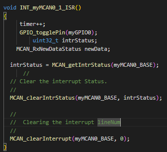
I have configured the can interrupt in sysconfig.just trying to receive and transmit the data from can  but interrupt is not getting triggered. in ISR just toggling LED.

 image.png image.png

  • Hi , can you please specify the example name.

    Could you also please tell whether you are using a launchpad or a control card ? Have you made sure your build configuration of project according to that .

    Regards

    Kunal 

  • Hello Kunal,

    i am using mcan_ex6_transmit_syscfg example and did few modifications for receiving purpose.

    using launchpad and done build configurations accordingly.

    ...

    Thanks!!

  • with polling transmit and receive working fine , with interrupt transmit and receive not working.

  • Hi Sayali,

    I saw the example does not support launchpad option out of the box.

    I only see build configuration for 

    Flash & Ram (These correspond to control card and there may be additional changes which may be required.)

    Typically for example having launchpad support output of the box we see launchpad configuration as shown below 


    Have you tried this : 

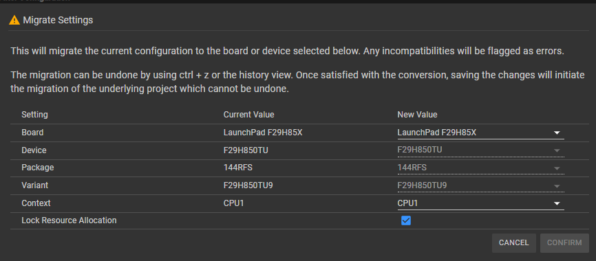
    * In syscfg  migration will be needed, change the board to launchpad and select appropriate pinmux in mcan configuration in syscfg , any other options that might need fixing   (You can refer the launchpad diagram present in sysfg or the  schematics)

    Let me know if this solves your issue.

    Regards

    Kunal.

  • Hello Kunal,

    i have did the below changes as per your suggestion

    getting below warnings. and still i saw build configuration for  Flash and RAM only.


    Thanks!!

    Sayali

  • Hi , Yes build configuration for that is not present out of box. After making the syscfg  changes , that configuration is equivalent to launchpad config. You can select any one of "RAM" or "Flash" build config now and try to run . Let me know if this didn't solve the issue. Will assign to someone from can team then.

    Regards

    Kunal.

  • Hello Kunal,

    after doing suggested changes interrupt is not getting triggered.

    kindly check on interrupt issue.

    Thanks

    Sayali

  • Hi Sayali , 

    Assigning this thread to someone from mcan team. 

    Mean while just to be sure , can you check if you have added this part of code in your program for enabling interrupts.

        //
        // Enable PIPE Global Interrupt (for INTs and RTINTs) and INT enable in CPU.
        //
        ENINT;
        Interrupt_enableGlobal();
     
    This should be present after board_init()
    Regards
    Kunal
  • Hello Kunal,

    Yes its added.

    Thanks!!

  • Hi, 

    Also i see


    in this only "Enable MCAN interrupt line 0 " is selected but register interrupt line0 handler is unchecked , can you please "check that" option and try. 

    (if want to register for both you can try enabling both line interupts in Enable Interrupt Line option )


    Also if you using any variable in ISR better to keep them volatile.

    I have requested to reassign someone from mcan team please expect a delay.

    Regards

    Kunal.

  • Hello Kunal,

    I have already tried with this changes.

    Thanks!!

  • Hi Sayali, 

    If possible can you share the Syscfg file which you are using? I can verify if the pinmux and CAN Clk tress is correct. 

    Regards,
    Pranav Siddappa

  • Hi Pranav,

    Please find the Syscfg file below.

    /**
     * These arguments were used when this file was generated. They will be automatically applied on subsequent loads
     * via the GUI or CLI. Run CLI with '--help' for additional information on how to override these arguments.
     * @cliArgs --device "F29H85x" --part "F29H850TU9RFS" --package "144RFS" --context "CPU1" --product "MCU_SDK_F29H85x@1.02.01.00"
     * @v2CliArgs --device "F29H850TU" --package "144RFS" --variant "TMS320F29H850TU9" --context "CPU1" --product "MCU_SDK_F29H85x@1.02.01.00"
     * @versions {"tool":"1.26.0+4407"}
     */
    
    /**
     * Import the modules used in this configuration.
     */
    const clocktree = scripting.addModule("/driverlib/clocktree.js");
    const gpio      = scripting.addModule("/driverlib/gpio.js", {}, false);
    const gpio1     = gpio.addInstance();
    const gpio2     = gpio.addInstance();
    const jtag      = scripting.addModule("/driverlib/jtag.js");
    const mcan      = scripting.addModule("/driverlib/mcan.js", {}, false);
    const mcan1     = mcan.addInstance();
    
    /**
     * Write custom configuration values to the imported modules.
     */
    const divider8       = system.clockTree["MCANACLKDIV"];
    divider8.divideValue = 10;
    
    const divider15       = system.clockTree["PLL_REFDIV"];
    divider15.divideValue = 1;
    
    const multiplier1         = system.clockTree["PLL_IMULT"];
    multiplier1.multiplyValue = 40;
    
    const mux7       = system.clockTree["OSCCLKSRCSEL"];
    mux7.inputSelect = "INTOSC2";
    
    gpio1.$name           = "myGPIO0";
    gpio1.direction       = "GPIO_DIR_MODE_OUT";
    gpio1.gpioPin.$assign = "GPIO19";
    
    gpio2.$name           = "myGPIO1";
    gpio2.gpioPin.$assign = "GPIO15";
    
    jtag.JTAG.$assign        = "JTAG";
    jtag.JTAG.tdoPin.$assign = "GPIO223/TDO";
    jtag.JTAG.tdiPin.$assign = "GPIO222/TDI";
    
    mcan1.$name                   = "myMCAN0";
    mcan1.additionalCoreConfig    = true;
    mcan1.stdFiltsUsed            = [0];
    mcan1.loopbackMode            = false;
    mcan1.dataRatePrescalar       = 0;
    mcan1.fdMode                  = false;
    mcan1.brsEnable               = false;
    mcan1.nomTimeSeg1             = 9;
    mcan1.nomTimeSeg2             = 8;
    mcan1.nomSynchJumpWidth       = 8;
    mcan1.nomRatePrescalar        = 3;
    mcan1.stdFilts                = 1;
    mcan1.enableInterrupt         = true;
    mcan1.interruptLine0Flag      = ["MCAN_IR_RF1N_MASK","MCAN_IR_TEFN_MASK"];
    mcan1.registerInterruptLine1  = true;
    mcan1.interruptLine1Flag      = ["MCAN_IR_RF1N_MASK","MCAN_IR_TEFN_MASK"];
    mcan1.txEventFIFOWaterMark    = 1;
    mcan1.rxFIFO1waterMark        = 1;
    mcan1.rxFIFO0waterMark        = 1;
    mcan1.interruptFlags          = ["MCAN_INTR_MASK_ALL"];
    mcan1.interruptLine           = ["MCAN_INTR_LINE_NUM_1"];
    mcan1.mcan.$assign            = "MCANA";
    mcan1.mcan.mcan_rxPin.$assign = "GPIO65";
    mcan1.mcan.mcan_txPin.$assign = "GPIO64";
    mcan1.periphClock.$name       = "driverlib_perClock0";
    mcan1.periphConfig.$name      = "driverlib_perConfig0";
    mcan1.stdFilt0.$name          = "stdFilt0";
    mcan1.stdFilt0.sfid1          = 4;
    mcan1.stdFilt0.sfec           = "MCAN_STDFILTEC_PRI_FIFO1";

    Thanks!!

  • Hi Sayali,

    Can you confirm that the expected Nominal bit rate is 250kbps and data bit rate is 2Mbps? Are you transferring and receiving with these bit rate configs?

    Regards, 
    Pranav Siddappa 

  • Hello Pranav,

    Yes its correct. same bit rate i hv configured in PCAN-View.

    Thanks!!

    Sayali

  • Hi Sayali, 

    Can you check with the file below? You can go ahead and suppress the warnings if you get any. 
    https://e2e.ti.com/cfs-file/__key/communityserver-discussions-components-files/81/untitled.syscfg

    Regards, 
    Pranav Siddappa

  • Hi Pranav,

    Getting error as below.

    Thanks!!

    Sayali

  • Hi Pranav,

    I have resolved the Error and tried flashing the code. but still interrupt is not getting triggered.

    Thanks!!

  • Hi Sayali, 

    I don't see any other issue that could hinder the working of this app. As a last resort, can you share the entire project? 
    I will try running it on my side and debug it line by line. 

    Regards, 
    Pranav Siddappa

  • Hello Pranav,

    Please find ISR and syscfg file below.

    void INT_myMCAN0_1_ISR()
    {
         timer++;
         GPIO_togglePin(myGPIO0);
             uint32_t intrStatus;
        MCAN_RxNewDataStatus newData;
    
      intrStatus = MCAN_getIntrStatus(myMCAN0_BASE);
    
        MCAN_writeMsgRam(myMCAN0_BASE, MCAN_MEM_TYPE_BUF, 1U, &txMsg);
    
        MCAN_txBufAddReq(myMCAN0_BASE, 1U);
    
        while(MCAN_getTxBufReqPend(myMCAN0_BASE))
        {
        }
    
      MCAN_clearIntrStatus(myMCAN0_BASE, intrStatus);
    
      MCAN_clearInterrupt(myMCAN0_BASE, 1);
    }

    /**
     * These arguments were used when this file was generated. They will be automatically applied on subsequent loads
     * via the GUI or CLI. Run CLI with '--help' for additional information on how to override these arguments.
     * @cliArgs --device "F29H85x" --part "F29H850TU9RFS" --package "144RFS" --context "CPU1" --product "MCU_SDK_F29H85x@1.02.01.00"
     * @v2CliArgs --device "F29H850TU" --package "144RFS" --variant "TMS320F29H850TU9" --context "CPU1" --product "MCU_SDK_F29H85x@1.02.01.00"
     * @versions {"tool":"1.26.0+4407"}
     */
    
    /**
     * Import the modules used in this configuration.
     */
    const clocktree = scripting.addModule("/driverlib/clocktree.js");
    const gpio      = scripting.addModule("/driverlib/gpio.js", {}, false);
    const gpio1     = gpio.addInstance();
    const gpio2     = gpio.addInstance();
    const jtag      = scripting.addModule("/driverlib/jtag.js");
    const mcan      = scripting.addModule("/driverlib/mcan.js", {}, false);
    const mcan1     = mcan.addInstance();
    
    /**
     * Write custom configuration values to the imported modules.
     */
    const divider4       = system.clockTree["EPWMCLKDIV"];
    divider4.divideValue = 1;
    
    const divider8       = system.clockTree["MCANACLKDIV"];
    divider8.divideValue = 10;
    
    const divider15       = system.clockTree["PLL_REFDIV"];
    divider15.divideValue = 1;
    
    const multiplier1         = system.clockTree["PLL_IMULT"];
    multiplier1.multiplyValue = 40;
    
    const mux7       = system.clockTree["OSCCLKSRCSEL"];
    mux7.inputSelect = "INTOSC2";
    
    gpio1.$name     = "myGPIO0";
    gpio1.direction = "GPIO_DIR_MODE_OUT";
    
    gpio2.$name = "myGPIO1";
    
    jtag.JTAG.$assign        = "JTAG";
    jtag.JTAG.tdoPin.$assign = "GPIO223/TDO";
    jtag.JTAG.tdiPin.$assign = "GPIO222/TDI";
    
    mcan1.$name                   = "myMCAN0";
    mcan1.additionalCoreConfig    = true;
    mcan1.stdFiltsUsed            = [0];
    mcan1.loopbackMode            = false;
    mcan1.dataRatePrescalar       = 0;
    mcan1.fdMode                  = false;
    mcan1.brsEnable               = false;
    mcan1.nomTimeSeg1             = 9;
    mcan1.nomTimeSeg2             = 8;
    mcan1.nomSynchJumpWidth       = 8;
    mcan1.nomRatePrescalar        = 3;
    mcan1.stdFilts                = 1;
    mcan1.enableInterrupt         = true;
    mcan1.interruptLine0Flag      = ["MCAN_IR_RF1N_MASK","MCAN_IR_TEFN_MASK"];
    mcan1.registerInterruptLine1  = true;
    mcan1.interruptLine1Flag      = ["MCAN_IR_RF1N_MASK","MCAN_IR_TEFN_MASK"];
    mcan1.txEventFIFOWaterMark    = 1;
    mcan1.rxFIFO1waterMark        = 1;
    mcan1.rxFIFO0waterMark        = 1;
    mcan1.interruptFlags          = ["MCAN_INTR_MASK_ALL"];
    mcan1.interruptLine           = ["MCAN_INTR_LINE_NUM_1"];
    mcan1.mcan.$assign            = "MCANA";
    mcan1.mcan.mcan_rxPin.$assign = "GPIO65";
    mcan1.mcan.mcan_txPin.$assign = "GPIO64";
    mcan1.periphClock.$name       = "driverlib_perClock0";
    mcan1.periphConfig.$name      = "driverlib_perConfig0";
    mcan1.stdFilt0.$name          = "stdFilt0";
    mcan1.stdFilt0.sfid1          = 4;
    mcan1.stdFilt0.sfec           = "MCAN_STDFILTEC_PRI_FIFO1";
    
    /**
     * Pinmux solution for unlocked pins/peripherals. This ensures that minor changes to the automatic solver in a future
     * version of the tool will not impact the pinmux you originally saw.  These lines can be completely deleted in order to
     * re-solve from scratch.
     */
    gpio1.gpioPin.$suggestSolution = "GPIO15";
    gpio2.gpioPin.$suggestSolution = "GPIO16";
    

  • Hi Sayali, 

    Can you confirm that this ISR is being meant for an RX? If its not possible to share the entire project, can you walk me through what you are trying to achieve here? I would like to understand the flow of how the ISR is expected to be triggered. 

    Regards, 
    Pranav Siddappa

  • Hi Pranav,

    In this program, the objective is to verify whether the Interrupt Service Routine (ISR) is being triggered correctly. Once the ISR functionality is confirmed, the same logic will be integrated into the main application code.

    In the current implementation, using  LINE1 interrupt.  RX FIFO1 new message interrupt, and TX event new message interrupt have been enabled. Within the ISR, a single LED is toggled to indicate interrupt execution, and a data transmission is performed as part of the interrupt handling routine.

    Please review and confirm whether any additional board-level configuration or hardware changes are required to ensure proper interrupt triggering and execution.

    Thanks!!

  • Hi Sayali, 

    Since ISR is not getting triggered, there is an issue with how the message is received. There might be the following issues:

    • Can you recheck the ID of the message?
    • Can you confirm if the Transceiver is connected correctly?
    • Also try tracing the signal you are sending to the CAN node via oscilloscope to check if the message is actually being sent out
    • There is a mismatch between the CAN mode and element size. Element size is 64 bytes and CAN FD mode is not enabled. Confirm which mode you want to use.

    As a last resort, try monitoring the RXBUF via the register window to confirm if the message has actually reached. 
    Its tough for me to recreate this without the entire project app. If you could share it as a whole, i might be able to prove more insight. 

    Regards, 
    Pranav Siddappa

  • Hi Pranav,

    Issue is still there , i have checked data is transmitting and receiving properly but interrupt is not getting triggered.

    Thanks !!

  • Hi Sayali, 

    Is there a possibility of sharing the entire app?

    Regards, 
    Pranav Siddappa

  • Hi Pranav,

    can u pls suggest how to share the entire project? i am unable to share zip file.

    Regards,

    Sayali

  • Hi Pranav,

    One additional observation I would like to share is as follows.

    When I run the example mcan_ex1_loopback_interrupts without making any modifications, I observe that the msgCount value is set to 1. Additionally, I am able to see the received messages in the RX buffer.

    However, after switching the board to 144RFS, the interrupt is not being triggered again. I also do not observe the expected interrupt behavior on this board.

    is there any board changes needed for 144RFS package please suggest.

    Regards,

    Sayali

  • Hi Sayali, 

    The mcan_ex1_loopback_interrupts example uses CANB instance which is not present on the Launchpad. You can change the instance to CANA/CANC along with the dedicated pins and it works. 
    These are the steps i followed: 

    • Change the config to Launchpad:

    • Change the CAN instance:
       
    • Build and run the app and check the msgCount variable:


    Below is the Launchpad pin out:
    F29H85X LP Pinout.pdf

    If you are observing Interrupt0 ISR then your observation is correct since it is not enabled. Hence it wont trigger. You can observe the interrupt1 ISR. 


    Regards, 
    Pranav Siddappa