This thread has been locked.

If you have a related question, please click the "Ask a related question" button in the top right corner. The newly created question will be automatically linked to this question.

TMS320F28379D: Multiple Sampling per Carrier frequency in ePWM

Part Number: TMS320F28379D


Hi all,

I am trying to generate gate pulses to the IGBTs of an inverter, and for this I am using the ePWM module (in CCS).

The problem I am facing is that I want to sample the sine wave multiple times (say (2^n)) per carrier cycle. I am unable to do this, as I am getting only one sample per carrier cycle. Please help.

I have attached the waveform (from PLECS) corresponding to (n=2), meaning (2^2 = 4) samples per carrier cycle.

I would appreciate any suggestions on how to achieve this using the ePWM module.

Thank you.
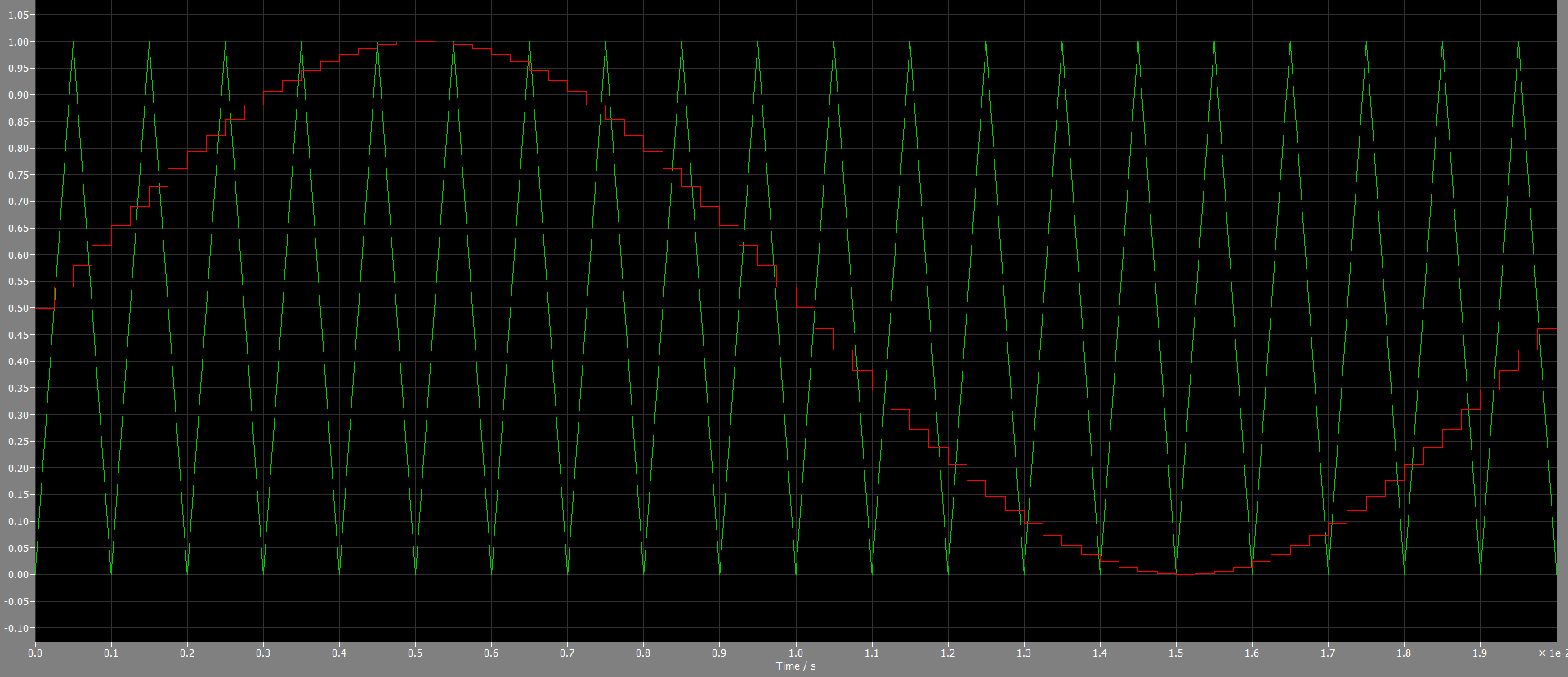
image.png

  • Hi Manish,

    The TMS320F28379D supports multiple ADC samples within a single PWM carrier period through several complementary mechanisms. Here's how to achieve this:

    Approach 1: ADC Trigger Repeater (Oversampling Mode)

    The most direct method uses the ADC Trigger Repeater module. Configure the repeater's NSEL parameter to generate multiple back-to-back SOC triggers from a single ePWM event for example, NSEL=3 produces 4 consecutive samples per trigger. Use the SPREAD parameter (in SYSCLK cycles) to distribute samples temporally across the PWM period rather than clustering them together [1].

    Approach 2: Dual ePWM Modules (Different Frequencies)

    Use one ePWM module for your carrier frequency and a second ePWM at an integer multiple frequency to trigger ADC SOCs at a higher rate. For example, ePWM1 at 2 kHz carrier with ePWM2 triggering ADC at 50 kHz gives 25 samples per carrier period [2][3]. The hardware-locked phase synchronization ensures cycle-by-cycle alignment between modules [4].

    Approach 3: Dual Interrupts via CMPA/CMPB Events

    To get two sampling points per carrier period, synchronize two ePWM modules and link their CMPA, CMPB, and TBPRD registers. Then configure:

    • ePWM1 interrupt on CMPA event (first sample point)
    • ePWM2 interrupt on CMPB event (second sample point)

    This produces identical waveforms from both modules while generating distinct interrupts at different points in the cycle [5]:

    1. C2000 Academy - ADC Trigger Repeater
    2. C2000 Academy - DMA Lab (ePWM ADC triggering)
    3. C2000 Academy - ePWM Module
    4. TMS320F28379D TRM - ePWM Synchronization
    5. TI E2E - Generate ePWM interrupt on both CMPA and CMPB

    Regards,
    Harisyam

  • Hi Harisyam, 

    Firstly thank you for the response. But my question is not related to ADC sampling. I am referring to the modulation reference used for PWM generation. Specifically, I would like to update the sinusoidal reference multiple times within a single carrier period (e.g., 4 times per carrier cycle as shown in the image) before comparison with the triangular carrier, similar to the attached PLECS implementation.

    Could you please suggest how this can be achieved using the ePWM module or interrupts/events on the F28379D? 

  • Hi Manish,

    You can have a second ePWM module configured at four times the frequency of first one. Here first ePWM is used for PWM generation. Use the second ePWM module to generate interrupt and update the modulation signal at a higher frequency than the first ePWM module.

    Thank you,
    Harisyam

  • Hi Harisyam,

    Thank you for your input. I was also thinking along the lines of using interrupts to update the sine value. Your suggestion of using a second ePWM module for this purpose has made the implementation much clearer.

    I will try this approach and let you know if it works.

    Thank you!

    Regards,
    Manish H T

  • Thank you for the update.

    Regards,
    Harisyam

  • Hi Harisyam,

    As mentioned earlier, I am using ePWM1 to generate interrupts, which are then used to update the sinusoidal reference values for ePWM2 and ePWM3.

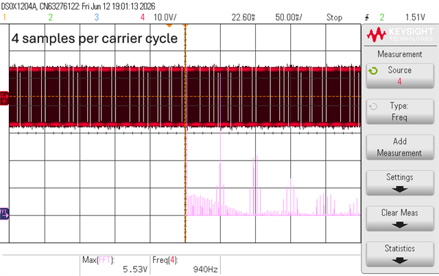
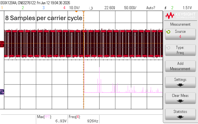
    To verify that the sine reference is being updated according to the intended sampling rate, I am operating a three-phase inverter and comparing the output voltage FFT with the corresponding simulation results. My assumption is that if the implementation is correct, the measured FFT should closely match the simulated FFT for the respective number of samples per carrier cycle.

    I have attached the FFT results (the inverter is operating under no-load conditions) for the following two cases:

    1. 4 samples per carrier cycle
    2. 8 samples per carrier cycle

    I observed that the FFT obtained for the 8-samples-per-carrier-cycle case matches the simulation reasonably well. However, the FFT for the 4-samples-per-carrier-cycle case differs significantly from the simulation results (I see some sub harmonics which should not be present). 

    I have also attached the relevant code for reference.

    Could you please review it and let me know if there is anything I might be overlooking in the implementation? In particular, I would like to confirm whether the sine reference is actually being updated at the intended rate and whether there are any ePWM configuration settings that could affect this behavior.

    Thank you for your time and assistance.

    Please use this link to access the images and code: https://drive.google.com/drive/folders/1ljcCQW_ms2Wjkh6LAadjdp6AKU9ge9EJ?usp=sharing 

    Regards,

    Manish H T

  • Hi Manish,

    What is the application that you are looking into?

    Why do you need to change the modulating signal multiple times within a switching/carrier cycle?

    Regards,
    Harisyam

  • Hi Harisyam,

    It is for research purpose, I am working on an analytical solution for obtaining the harmonic spectra. Hence for this I will be requiring multiple times sampling per carrier cycle. Right now I am facing the above mentioned issue with the code, there is some part of the code which is creating those sub harmonics, and I am trying to figure it out and fix it. 

    Regards, 

    Manish H T

  • Hi Manish,

    You can also put the sensed value through DAC to at the same frequency as ADC sensing within the interrupt to confirm if you have the values sensed as per your requirement. You may also store a couple of samples in an array to save it as csv file to inspect the sampled values offline. Then you will be able to identify the root cause of mismatch in FFT.

    Regards,
    Harisyam

  • Hi Harisyam,

    Thank you for your quick response and for taking the time to help.

    I wanted to let you know that I have verified the modulating wave update both through data logging and using the DAC module (as seen in the images). The results obtained confirm that the code is functioning as expected.

    Based on these observations, I am confident that the implementation is working correctly. However, the FFT issue still remains unresolved (the subharmonics still appear).

    Thank you once again for your support.

    Regards,
    Manish H T

  • Hi Manish,

    Thank you for the update.

    Regards,
    Harisyam

  • Hi Harisyam,

    Hope your are doing well. I found the reason behind the subharmonics which were appearing on the scope. It is due to missing of one gating pulse and thus the duty changes and sub harmonics appear. 

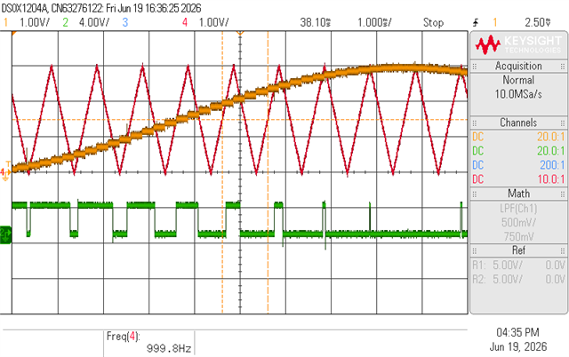
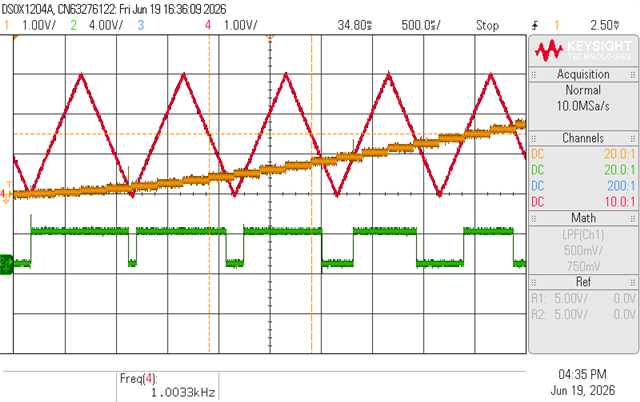
    I observed on the oscilloscope that the gating signal is not being generated for a particular carrier cycle by the F28379D Launchpad as seen in the image (the images are the output of the launchpad and not the inverter, I am testing the gate signals before I give to the inverter). And this happens for every sine or modulating cycle at the same instant. I feel this is because of the intersection of carrier with sine wave is happening during update of the sine wave(as seen in the image), and not before or after the update.

    I have tried this with different cases where I update the sine wave multiple times per carrier wave (let's say 6 times or 10 times or n times), every time this scenario of intersection between carrier and sine happening during the update of sine wave, there is no gating signal.

    I have attached my code too, could you please help me with this issue.

    Use this link for the code that I have used:  CLICK HERE TO SEE THE CCS CODE THAT I HAVE USED (I have summarized the code in readme file)

    (Please use this link if the above isn't opening: https://drive.google.com/drive/folders/1lKnzDKwUWMQErzT-vis0nendSC3Z1mSA?usp=sharing ) (I have summarized the code in readme file)

    The below image is a zoomed-in version of what is happening: We can clearly see the intersection is happening between the transition of update of the sine value

    The below image is a bit zoomed-out version of the same:

    The below image is to show that it happens every sine cycle at the same instant:

    Thank you,

    Warm regards,

    Manish H T

  • Hi Manish,

    Can you say what is the application you are looking at? 

    What is the action qualifier configuration you have used in the code? Do you change the PWM configuration within the line cycle?

    If you are not changing the action qualifier function in between, you can put the value of counter compare in the DAC and observe the reason for skipping the pulse. This should help you narrow down the reason for pulse skipping.

    Regards,
    Harisyam