This thread has been locked.

If you have a related question, please click the "Ask a related question" button in the top right corner. The newly created question will be automatically linked to this question.

MSP430-SDK: Schematic Verification

Part Number: MSP430-SDK
Other Parts Discussed in Thread: TPD4E1U06, MSP430FR6047, MSP430FR6043, MSP-FET

MSP430FR6043.pdf 

  • Hi Ashok,

    We typically do schematic reviews on friday where the whole MSP hardware customer support team reviews the schematic together. Would you be ok with waiting till friday so we can give this a thorough review with the team?

  • Hi Ashok,

    According to the schematic, it should be used in water meter application, please see my comments below.

    1. Please ensure proper isolation between different ground planes(GND/USS_GND/RF_GND), based on the current schematic, it seems that all grounds use the same symbol and there is no clear different network labels.

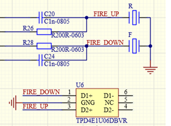
    2. USS_IN should be carefully protected since it can be damaged by the electrostatic breakdown if the device will run in a harsh environment based on our experience, so it is recommended to reserve the ESD protection circuits space in the board for backup, like using the TVS tube TPD4E1U06 to do the protection as shown below.

    3. It seems your Pin71 PVCC1 isn't connected, please make sure all the VCC and GND pins have proper connected.

    4. We connect JTAG_TXD and JTAG_RXD to the UART TXD/RXD for data transmission, but it seems you didn't connect them to the UART pin, however, if you don't use them for the communication, it should be fine, please double check it.

    Thanks

    Best Regards,
    Peter

  • We used initially for water meter application MSP430FR6047 which is connected to spool directly from controller without additional circuitry(series capacitors and resistors), here in MSP430FR6043 we have seen OPA836IDBVT,SN74LVC2T45DCTR and TS5A9411DCKR chips and additional components required for spool connection please check and confirm. we want only water meter application we need exact spool circuit for water meter. please share the sample diagram if available.

  • Hi Ashok,

    I believe you have checked the TIDM-02005 Schematic which contains many analog components that specially required by gas application, but if you take a look at the MSP430FR6043 reference design guide for water meter: TIDM-02005 Reference Design "Chapter 3.1.1.1.1 Hardware Modifications for Water Meter Operation" as shown below, you will find that it need to remove the jumpers to disable these components so that can be used for the water application, which is almost the same as the design with MSP430FR6047, so it should be fine of your current schematic with no additional circuitry.

    Best Regards,
    Peter

  • Hi Sir,

    Please find the updated schematic attached for your verification.

    For the water meter application, we require interfaces for the display, SPI, and spool connection. In addition, we need two UARTs:

    1. One UART for debug purposes.
    2. One UART for communication with the sensor.

    However, based on the current pin allocation, all available pins appear to be assigned. Could you please review the schematic and suggest if any alternate pins can be configured and used as an additional UART while meeting the display, SPI, and spool interface requirements?

    Please let us know your recommendations.

    Thanks and Regards,

    1. Rajesh M
  • Hi Ashok,

    If you use the Spy-Bi-Wire (SBW) to flash the firmware and code debug, which only acquire 4 pins(TEST, RESET, VCC, VSS), then you can use pin 19 and pin 20 as another UART.

    Best Regards,
    Peter

  • Hi Sir,

    Thanks for the review.

    We have an MSP-FET debugger available and will perform the required testing and update you with the results.

    Apart from the debugging aspect, could you please review and confirm whether the schematic is suitable for the water meter application, or if any additional circuitry/components need to be incorporated? Since we are planning to proceed with PCB design shortly, we would like to finalize the schematic before moving to the layout stage.

    Please share your suggestions and recommendations.

    Thanks & Regards,

    Rajesh M

  • Hi sir,

    As per your suggestion we have tested the programming and debug using MSP-FET debugger with 4 pins (TEST, RESET, VCC, VSS) with MSP430FR6047 board(already board is available with us) but its failing , but if we connect  1-VCC;2 -TEST;3- TDO;4- TDI ; 5- TMS; 6- TCK; 7 -RESET ; 8- GND its programming and working with same MSP-FET debugger. what could be the issue we are using Code composer Studio 12.8.1. 

  • Hi sir,

    we are still waiting for the response could you please check and update.

    Rajesh M

  • Hi Rajesh,

    Regarding the schematic,

    1. Regarding your spool/transducer connection, please remove the R75 and R74, or place them to the connector J4 side not MCU side as shown below.

    2. For the PVCC1, it should be from the same source as your PVCC which filtered with capacitors by the VCC, it shouldn't be connected directly to VCC.

    Besides the two points mentioned above, it looks fine for the water application.

    Regarding the SBW debug with MSP-FET, please follow below connection and try again.

    TEST(Board) --> TCK(MSP-FET)

    RESET(Board) -> TDO/TDI(MSP-FET)

    Best Regards,
    Peter

  • Hi sir,

    I have connected below connections on both sides,

     Board (CON1)                        MSP-FET

    1) VCC( 1st pin) ==========>4  (VTARGET)

    2) GND(8th pin) ===========>9 th pin 

    3)TEST/SBWTCK (2nd pin) =========> 7 ( SBWTCK)

    4)RST/NMI/SBWTDIO ( 7 th pin)=======>1 (SBWTDIO)

       still not programming with above 4 pin connections any thing settings required on CCS side please suggest, same if we try with 8 pin connector with MSP-FET its working.

  • Hi Ashok,

    No need to modify in the CCS, please try to connect board VCC to MSP-FET VCC_TOOL(Pin 2), it may be caused by the insufficient power supply. Additionally, the board can be powered individually, then only connect the GND, TEST, RESET with the MSP-FET should be fine.

    Best Regards,
    Peter