MSPM0-SDK: XDS110 Probe, MSPM0G1507

Part Number: MSPM0-SDK
Other Parts Discussed in Thread: MSPM0G1507, LP-XDS110ET, LP-MSPM0G3507, MSPM0G3507

Hello,


This is Woojun Lee, a Ph. D student advised by Dr. Jeffrey Sean Walling at Virginia Tech ECE.


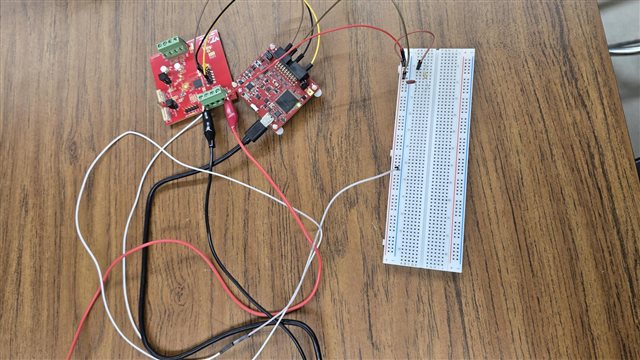
I am trying to connect MSPM0G1507 through XDS110 USB Debug Probe to my laptop but I could not. Seems that I am missing some connections or made some wrong connections. I need help with this.


Sincerely,

Woojun Lee

540-605-0694

  • Hi Woojun,

    Can you provide more details for the issue you're seeing?

    • Have you previously been able to connect?
      • if so, are you now facing issues connecting to the DAP or CortexM0?
    • Is your laptop correctly identifying XDS110?
    • Can you share a schematic of the programmer header, or are you using a Launchpad's programming headers?

    Best Regards,
    Brian

  • Hello Brian,

    I was never able to connect to MSPM0G1507 through XDS110 USB Debug probe.

    Seems that laptop is correctly identifying XDS110 through TI CCS IDE.

    I am connecting some of the CTI-20 pins in debug probe (SWDIO, SWCLK, NRESET, GND) pins to MCU. I have connected 3.3V VDD to EXT VDD in debug probe and MCU.

    I am consistently facing the error below.

    This error is generated by TI's USCIF driver or utilities. The value is '-615' (0xfffffd99). The title is 'SC_ERR_SWD_PROTOCOL'. The explanation is: The target failed to see a correctly formatted SWD header. The connection to the target may be unreliable. Try lowering the TCLK setting before trying again.

    Sincerely,
    Woojun
  • Hi Woojun,

    Can you check the following XDS110 connections:

    • CTI-20 pin 1: SWDIO
    • CTI-20 pin 5: VTREF
    • CTI-20 pin 8, or 10, or 12, or 16: GND
    • CTI-20 pin 11: SWCLK

    Additionally, please ensure all grounds are shared between the XDS110, target device, and external power supply.

    Lastly, how long are your programming cables? We generally recommend these not be longer than 30cm, as anything longer may mess with timings. You can also manually lower the SWD speed from the target configuration file by selecting the debug probe and advanced options. 

    Best Regards,
    Brian

  • Hello Brian. I was not using VTREF. Is this different from VDD?

  • Hi Woojun,

    VTREF is used by the programmer to verify the target MCU has power. Are you using pins on the Auxilary debug header and/or the probe expansion header?

    Best Regards,
    Brian

  • Hello Brian, I am connecting CTI-20 header from debug probe. We made our custom board that has MSPM0G1507 mounted. I just tried connecting VTRef to 3.3V, which is a supply of the MSPM0G1507, but still sees the same error.


  • Seems that the configuration left is correct... right? I was using the right configuration

  • Hi Woojun,

    Apologies, I was thinking you were using the following version of the debug probe: TMDSEMU110-U Debug probe | TI.com. This uses the pinout shown on the right. It looks like youre using the LP-XDS110ET.

    From the schematic:

    It appears to match the graphic on the left. Does that configuration work? I will say this specific XDS110 version was meant for Wireless connectivity MCUs, but I believe it should still work with MSPM0.

    Best Regards,
    Brian

  • Hello, Brian.

    I should definitely purchase TMDSEMU110-U Debug probe | TI.com to debug my MSPM0G1507.

    It seems that 20-pin connectors are for debugging launch-pad. And I noticed that there is a 10-pin debug connector that allows for a custom board. However, I could not locate that pin information. Could you guide me to use that 10-pin debug connector before my newly ordered debug probe arrives?

  • Hi Woojun,

    Here is the pinout for the 10-pin connector for the LP-XDS110ET:

    All design files for this debug probe can be found here: LP-XDS110ET Development kit | TI.com

    Best Regards,
    Brian

  • Hello Brian,

    I made this connection but it is still not working.

    I would need to purchase alternative debug probes other than TMDSEMU110-U Debug probe | TI.com, since this is out of stock now.

    Are there any lists that I can refer to for purchasing mspm0-compatible debug probes?

  • Hi Woojun,

    The XDS110 attached to any of our MSPM0 launchpads will work. The cheapest will be the LP-MSPM0L1117 Evaluation board | TI.com with all standard connections (GND,3v3,5v5, TX,RX, NRST,SWDIO,SWCLK, and BSL).

    Best Regards,
    Brian

  • Hello Brian,

    Thanks for the suggestion. We do have lp-mspm0g3507.

    However, my labmate tried debugging our mspm0 using this but could not since this already has connection between a mcu on the board. Should we take that mcu on the launch-pad out to debug our mspm0 on the other board?

    Thanks for your time.

  • Hello, Brian,

    I just followed the manual below but still got the same error.. 

  • Hi Woojun,

    A few more things to try:

    1. Can you disconnect all jumpers J101 and use your jumper wires to connect the custom board directly to the XDS110 side of the LP instead of the 10-pin header on J102? 
    2. Does adjusting the speed of the Connection properties of the XDS110 in the .ccxml still result in the same error? By default, the XDS110 is also set to have power supplied from the target so external power to your mcu is still required.

    If neither of the above work, can you share the schematic for your custom board? 

    Best Regards,
    Brian

  • Hello, Brian.

    1. I tried both connecting J101 to mspm0G1507 and J102 with msmpm05G107 but neither of them works. However, using J101 to debug mspm0g3507 on the launchpad works, which means the xds110 debug probe is working. Therefore, it must be the problem in the connection between my custom board and the xds110 debug probe.

    2. I tried adjusting the clock speed and the power setting. I tried feeding vtref from 10 pin cortex pins to the mspm0 and external power supply to the mspm0. However, neither of them does not work. It consistently throws The value is '-615' (0xfffffd99). The title is 'SC_ERR_SWD_PROTOCOL'.

    Unfortunately, I don't have any schematic but layout as below. Seems that connection matches 48-pin version of mspm0g1507.

    3. Currently, I have resistors/caps on the left are mounted but no resistors on the right are soldered yet. Do you think that the right resistors are MUST for debug tool to work?

    Sincerely,

    Woojun

  • Hi Woojun,

    Sorry for the delayed response. This is looking like a hardware failure. Can you replace the jumpers on J101 of the Launchpad with your cables, and try programming the G3507? If this works, it points to there being a board failure. 

    Best Regards,
    Brian