This thread has been locked.

If you have a related question, please click the "Ask a related question" button in the top right corner. The newly created question will be automatically linked to this question.

LP-MSPM0L1306: Setting up both OPAs for differential input

Part Number: LP-MSPM0L1306
Other Parts Discussed in Thread: SYSCONFIG

Hello,

I am currently prototyping a system that will use a sensor with a differential output. When configuring the OPA's through the system configuration, and following the given example in the techinical reference manual, my voltage across the inputs jumps from expected mV output to a voltage around 1.5V. Maybe, I am misinterpreting the reference manual that everything will be handled internally, but some help would be appreciated.
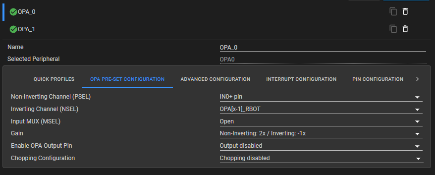
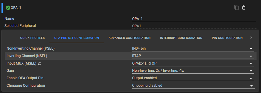
image.png

image.png

  • Hi Joseph,
    The ~1.5 V output is the OPA settling to approximately VDDA/2. This is most likely the OPA's internal gain network being active (mselChannel ≠ DL_OPA_MSEL_OPEN) with no proper external feedback circuit.

    The M0L1306 OPAs do not not have a built-in differential-subtraction mode.

    The TRM's differential example describes an external 2-OPA instrumentation amplifier (INA) circuit that requires external resistors.

    Some recommendations are the following:

    1. In SysConfig, set MSEL = Open for both OPA0 and OPA1. This is the most likely source of the 1.5 V issue.

    2. Add the external resistor network. Without it the OPAs have no closed feedback loop and will rail or float to mid-supply

    3. Verify OPA0.IN0− (PA24) and OPA1.IN0− (PA17) connect only to their external feedback nodes, not shorted directly to output pins

    You can use the Two OPA Instrumentation Amplifier With M0 Devices as a reference.

    Best Regards,

    Diego Abad