


Part Number: TMS320F28P650DH
Hello,
When trying to flash CPU2 from code composer I am getting an error
C28xx_CPU2: Flash Programmer: Error erasing Bank 2 FMSTAT (STATCMD on some devices) value = 65. Operation Cancelled (0).
C28xx_CPU2: File Loader: Memory write failed: Unknown error
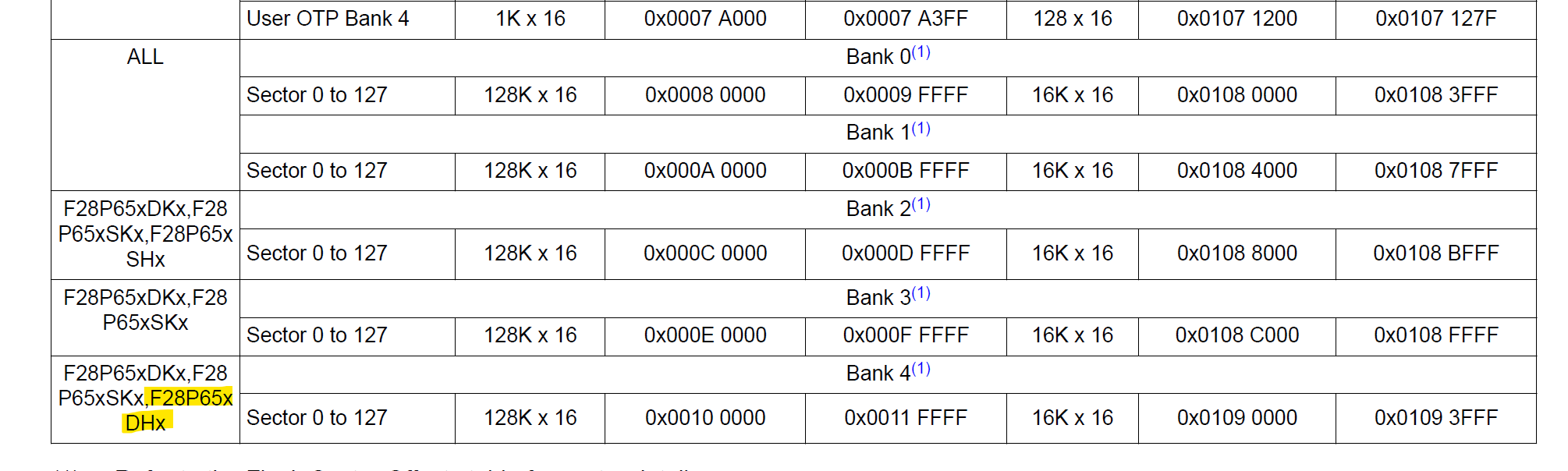
However, the DH6 does not have a Bank 2 of Flash only 0,1 and 4.
I have the correct device number set in the project properties and the target config, so I don't know where the Bank 2 setting is coming from. Flash settings in debug config only list Banks 0, 1, and 4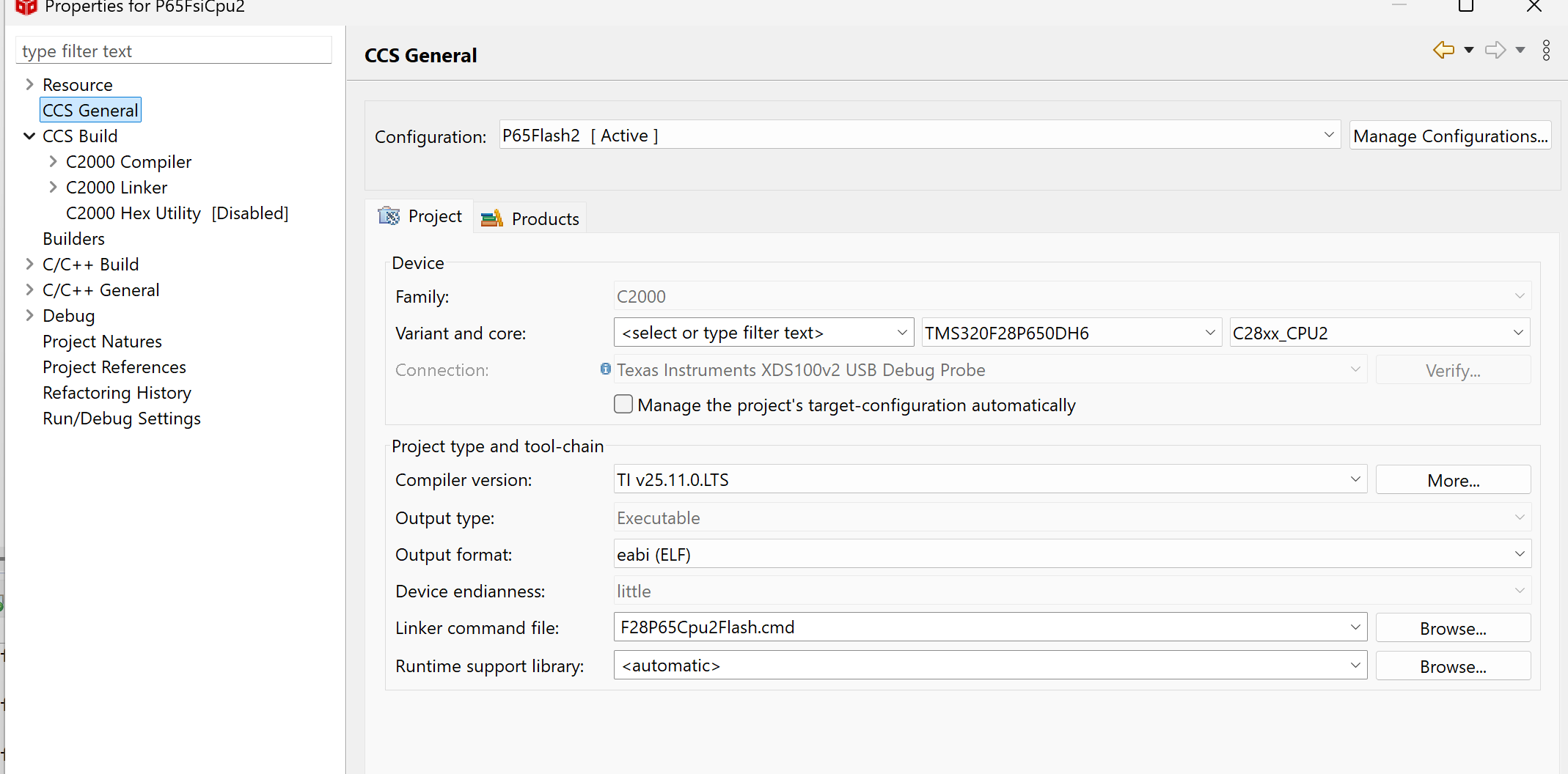
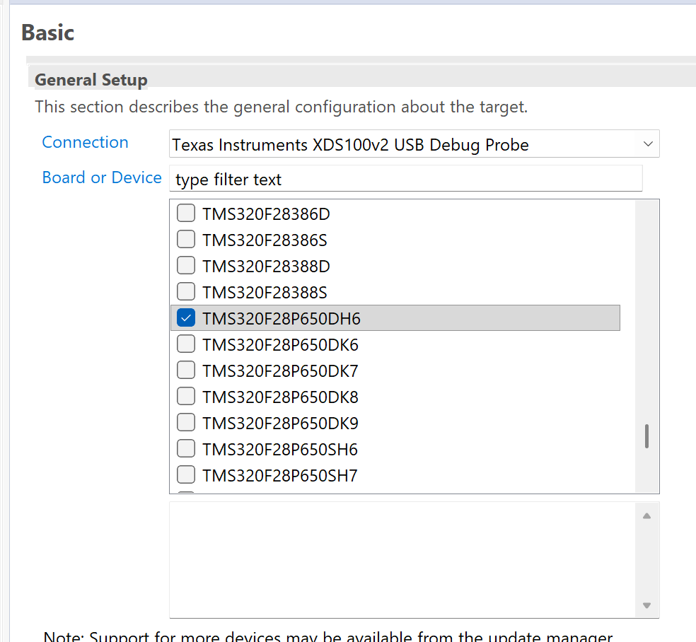
Additionally from console output CPU1 is trying to erase Banks 0-3 so there seems to be a settings issue I am unaware of that is messing up intialization values
C28xx_CPU1: GEL Output:
Memory Map Initialization Complete
C28xx_CPU1: GEL Output: ... DCSM Initialization Start ...
C28xx_CPU1: GEL Output: ... DCSM Initialization Done ...
C28xx_CPU1: GEL Output:
CPU2 is out of reset and configured to wait boot.
(If you connected previously, may have to resume CPU2 to reach wait boot loop.)
C28xx_CPU1: If erase/program (E/P) operation is being done on one core, the other core should not execute from shared-RAM (SR) as they are used for the E/P code. User code execution from SR could commence after the selected CPU1/CPU2 flash banks executable are programmed.
C28xx_CPU1: Only CPU1 on-chip Flash Plugin can configure clock for CPU1, and CPU2 Flash operations. Plugin automatically configures PLL when CPU1 Flash operations are invoked. However, if users want to do only CPU2 Flash operations without doing a prior CPU1 operation in the current session, they should click on 'Configure Clock' button in CPU1's on-chip Flash Plugin before invoking CPU2 Flash operations. When this button is used, Flash Plugin will configure the clock for CPU1/CPU2 at 200MHz using INTOSC as the clock source. Plugin will leave PLL config like this and user application should configure the PLL as required by application.
C28xx_CPU1: Before doing any flash operations using the flash plugin, (a) Please select which flash banks should be mapped to which CPU (CPU1 vs CPU2) - This selection should be done in CPU1 flash plugin GUI. (b) Please select the flash banks that the user would like the flash plugin to erase (in the CPU1 flash plugin GUI and the CPU2 flash plugin GUI)
C28xx_CPU1: GEL Output: ... DCSM Initialization Start ...
C28xx_CPU1: GEL Output: ... DCSM Initialization Done ...
C28xx_CPU1: GEL Output:
CPU2 is out of reset and configured to wait boot.
(If you connected previously, may have to resume CPU2 to reach wait boot loop.)
C28xx_CPU1: Writing Flash @ Address 0x00080000 of Length 0x00000002 (page 0)
C28xx_CPU1: GEL Output: ... DCSM Initialization Start ...
C28xx_CPU1: GEL Output: ... DCSM Initialization Done ...
C28xx_CPU1: GEL Output:
CPU2 is out of reset and configured to wait boot.
(If you connected previously, may have to resume CPU2 to reach wait boot loop.)
C28xx_CPU1: GSxMSEL register configured correctly
C28xx_CPU1: BankMuxSel register configured correctly
C28xx_CPU1: PLL configuration status = 1. PLL configured successfully.
C28xx_CPU1: Erasing Flash Bank 0
C28xx_CPU1: Erasing Flash Bank 1
C28xx_CPU1: Erasing Flash Bank 2
C28xx_CPU1: Erasing Flash Bank 3
C28xx_CPU1: Data has been buffered at the end of the current data block for 64-bit aligned writes.
C28xx_CPU1: Writing Flash @ Address 0x00080008 of Length 0x00000b09 (page 0)
C28xx_CPU1: Data has been buffered at the end of the current data block for 64-bit aligned writes.
C28xx_CPU1: --Verifying Flash @ Address 0x00080008 of Length 0x00000B08
C28xx_CPU1: Writing Flash @ Address 0x00080b18 of Length 0x0000005b (page 0)
C28xx_CPU1: Data has been buffered at the end of the current data block for 64-bit aligned writes.
C28xx_CPU1: --Verifying Flash @ Address 0x00080B18 of Length 0x00000058
C28xx_CPU1: Writing Flash @ Address 0x00080b78 of Length 0x00000044 (page 0)
C28xx_CPU1: --Verifying Flash @ Address 0x00080B78 of Length 0x00000044
C28xx_CPU1: Writing Flash @ Address 0x00080bc0 of Length 0x00000012 (page 0)
C28xx_CPU1: Data has been buffered at the end of the current data block for 64-bit aligned writes.
C28xx_CPU1: --Verifying Flash @ Address 0x00080BC0 of Length 0x00000010
C28xx_CPU1: Writing buffered data @ Address 0x00080000 of Length 0x00000004
C28xx_CPU1: --Verifying Flash @ Address 0x00080000 of Length 0x00000004
C28xx_CPU1: Writing buffered data @ Address 0x00080B10 of Length 0x00000004
C28xx_CPU1: --Verifying Flash @ Address 0x00080B10 of Length 0x00000004
C28xx_CPU1: Writing buffered data @ Address 0x00080B70 of Length 0x00000004
C28xx_CPU1: --Verifying Flash @ Address 0x00080B70 of Length 0x00000004
C28xx_CPU1: Writing buffered data @ Address 0x00080BD0 of Length 0x00000004
C28xx_CPU1: --Verifying Flash @ Address 0x00080BD0 of Length 0x00000004
C28xx_CPU2: GEL Output:
RAM initialization done
C28xx_CPU2: GEL Output:
Memory Map Initialization Complete
C28xx_CPU2: If erase/program (E/P) operation is being done on one core, the other core should not execute from shared-RAM (SR) as they are used for the E/P code. User code execution from SR could commence after the selected CPU1/CPU2 flash banks executable are programmed.
C28xx_CPU2: Only CPU1 on-chip Flash Plugin can configure clock for CPU1, and CPU2 Flash operations. Plugin automatically configures PLL when CPU1 Flash operations are invoked. However, if users want to do only CPU2 Flash operations without doing a prior CPU1 operation in the current session, they should click on 'Configure Clock' button in CPU1's on-chip Flash Plugin before invoking CPU2 Flash operations. When this button is used, Flash Plugin will configure the clock for CPU1/CPU2 at 200MHz using INTOSC as the clock source. Plugin will leave PLL config like this and user application should configure the PLL as required by application.
C28xx_CPU2: Before doing any flash operations using the flash plugin, (a) Please select which flash banks should be mapped to which CPU (CPU1 vs CPU2) - This selection should be done in CPU1 flash plugin GUI. (b) Please select the flash banks that the user would like the flash plugin to erase (in the CPU1 flash plugin GUI and the CPU2 flash plugin GUI)
C28xx_CPU2: Writing Flash @ Address 0x00100000 of Length 0x00000002 (page 0)
C28xx_CPU2: GSxMSEL register configured correctly
C28xx_CPU2: Erasing Flash Bank 2
C28xx_CPU2: Flash Programmer: Error erasing Bank 2 FMSTAT (STATCMD on some devices) value = 65. Operation Cancelled (0).
C28xx_CPU2: File Loader: Memory write failed: Unknown error
C28xx_CPU2: GEL: File: C:


