This thread has been locked.

If you have a related question, please click the "Ask a related question" button in the top right corner. The newly created question will be automatically linked to this question.

How to create a target configuration for TMS320C6204

Other Parts Discussed in Thread: TMS320C6204

I'm new to this whole world and want to connect an XDS-560v2 to a TMS320C6204 DSP device via JTAG but I don't see the option in Code Composer.  I've seen this guide:

http://processors.wiki.ti.com/index.php/Target_Configuration_-_Custom_Configurations

but honestly have no idea what it is doing or how it came to the conclusion to use one thing over another.


Can anyone help me?

  • Hi Chris,

    The advanced option requires a bit of knowledge on how the JTAG chain is configured. If you don't know, it would be confusing. What exact XDS560v2 emulator are you using? Give the exact name and vendor.

    Thanks

    ki

  • I haven't purchased it yet so if there is a particular tool that would make connecting CCS to this device I would love to here it. 

    I was planning on getting this http://store.blackhawk-dsp.com/default/blackhawk-jtag-emulators/xds560v2-stm-emulators/usb560v2-stm-emulator-usb-only.htm

  • The XDS560v2 is a good emulator. I created a target configuration for it (using a C6204) and attached it here.

    Thanks

    ki

    2330.C6204_via_BHXDS560v2.ccxml

  • Thanks for the help.  I'll let you know if it works when the debugger arrives.

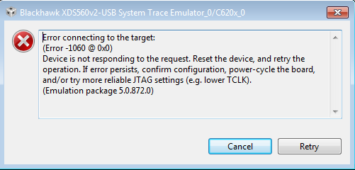
  • It didn't work.  I know the pins are correct and I'm not using any extension cables to connect so I can only imagine the problem is in the CCXML file.

    Here is the error.

    Any Ideas?

  • Try lowering the TCLK value as mentioned (start low, maybe with 2.0). If that doesn't help, please test your connection and post the results.

    Thanks

    ki

  • I tried messing with TCLK but no value seemed to change anything.  Below are the Test Connection results.

    [Start]

    Execute the command:

    %ccs_base%/common/uscif/dbgjtag.exe -f %boarddatafile% -rv -o -F inform,logfile=yes -S pathlength -S integrity

    [Result]


    -----[Print the board config pathname(s)]------------------------------------

    C:\Users\NVD\AppData\Local\.TI\1378298878\

        0\0\BrdDat\testBoard.dat

    -----[Print the reset-command software log-file]-----------------------------

    This utility has selected a 560/2xx-class product.

    This utility will load the program 'bh560v2u.out'.

    The library build date was 'Oct  3 2012'.

    The library build time was '22:14:17'.

    The library package version is '5.0.872.0'.

    The library component version is '35.34.40.0'.

    The controller does not use a programmable FPGA.

    The controller has a version number of '5' (0x00000005).

    The controller has an insertion length of '0' (0x00000000).

    The cable+pod has a version number of '8' (0x00000008).

    The cable+pod has a capability number of '7423' (0x00001cff).

    This utility will attempt to reset the controller.

    This utility has successfully reset the controller.


    -----[Print the reset-command hardware log-file]-----------------------------


    The scan-path will be reset by toggling the JTAG TRST signal.

    The controller is the Nano-TBC VHDL.

    The link is a 560-class second-generation-560 cable.

    The software is configured for Nano-TBC VHDL features.

    The controller will be software reset via its registers.

    The controller has a logic ZERO on its EMU[0] input pin.

    The controller has a logic ZERO on its EMU[1] input pin.

    The controller will use falling-edge timing on output pins.

    The controller cannot control the timing on input pins.

    The scan-path link-delay has been set to exactly '2' (0x0002).

    The utility logic has not previously detected a power-loss.

    The utility logic is not currently detecting a power-loss.

    Loaded FPGA Image: B:\ti\ccsv5\ccs_base\common\uscif\dtc_top.jbc


    -----[The log-file for the JTAG TCLK output generated from the PLL]----------


      Test  Size   Coord      MHz    Flag  Result       Description

      ~~~~  ~~~~  ~~~~~~~  ~~~~~~~~  ~~~~  ~~~~~~~~~~~  ~~~~~~~~~~~~~~~~~~~

        1   none  - 07 13  10.13kHz   -    similar      isit internal clock

        2   none  - 07 1E  11.47kHz  {-}   similar      isit internal clock

        3    512  - 07 13  10.13kHz   O    good value   measure path length

        4    512  - 07 13  10.13kHz  {O}   good value   apply explicit tclk


    The first internal/external clock test resuts are:

    The expect frequency was 10131Hz.

    The actual frequency was 10131Hz.

    The delta frequency was 0Hz.


    The second internal/external clock test resuts are:

    The expect frequency was 11474Hz.

    The actual frequency was 11473Hz.

    The delta frequency was 1Hz.


    In the scan-path tests:

    The test length was 16384 bits.

    The JTAG IR length was 4 bits.

    The JTAG DR length was 1 bits.


    The IR/DR scan-path tests used 4 frequencies.

    The IR/DR scan-path tests used 10.13kHz as the initial frequency.

    The IR/DR scan-path tests used 11.47kHz as the highest frequency.

    The IR/DR scan-path tests used 10.13kHz as the final frequency.


    -----[Measure the source and frequency of the final JTAG TCLKR input]--------


    The frequency of the JTAG TCLKR input is measured as 10.13kHz.


    The frequency of the JTAG TCLKR input and TCLKO output signals are similar.

    The target system likely uses the TCLKO output from the emulator PLL.


    -----[Perform the standard path-length test on the JTAG IR and DR]-----------


    This path-length test uses blocks of 512 32-bit words.


    The test for the JTAG IR instruction path-length succeeded.

    The JTAG IR instruction path-length is 4 bits.


    The test for the JTAG DR bypass path-length succeeded.

    The JTAG DR bypass path-length is 1 bits.


    -----[Perform the Integrity scan-test on the JTAG IR]------------------------


    This test will use blocks of 512 32-bit words.

    This test will be applied just once.


    Do a test using 0xFFFFFFFF.

    Scan tests: 1, skipped: 0, failed: 0

    Do a test using 0x00000000.

    Scan tests: 2, skipped: 0, failed: 0

    Do a test using 0xFE03E0E2.

    Scan tests: 3, skipped: 0, failed: 0

    Do a test using 0x01FC1F1D.

    Scan tests: 4, skipped: 0, failed: 0

    Do a test using 0x5533CCAA.

    Scan tests: 5, skipped: 0, failed: 0

    Do a test using 0xAACC3355.

    Scan tests: 6, skipped: 0, failed: 0

    All of the values were scanned correctly.


    The JTAG IR Integrity scan-test has succeeded.


    -----[Perform the Integrity scan-test on the JTAG DR]------------------------


    This test will use blocks of 512 32-bit words.

    This test will be applied just once.


    Do a test using 0xFFFFFFFF.

    Scan tests: 1, skipped: 0, failed: 0

    Do a test using 0x00000000.

    Scan tests: 2, skipped: 0, failed: 0

    Do a test using 0xFE03E0E2.

    Scan tests: 3, skipped: 0, failed: 0

    Do a test using 0x01FC1F1D.

    Scan tests: 4, skipped: 0, failed: 0

    Do a test using 0x5533CCAA.

    Scan tests: 5, skipped: 0, failed: 0

    Do a test using 0xAACC3355.

    Scan tests: 6, skipped: 0, failed: 0

    All of the values were scanned correctly.


    The JTAG DR Integrity scan-test has succeeded.


    [End]

  • Looks like the JTAG scan tests passed. This means that your JTAG connectivity between the PC and your target is good. This also means the CCXML file is good.

    Lets enable some additional diagnostics logging. Please use the CCS Support dialog to enable Debug Server Logging (this file is NOT enabled by default). Once enabled, try to start a debug session again and connect (reproduce the problem). Shut down the debugger and zip up the generated log file and attach it here.

    Thanks

    ki

  • Here you go.  Thanks again.

    8233.TMS320C6204.log

  • Thanks Chris,

    Unfortunately it didn't give us the additional insight we were hoping for.

    Could you tell me more about your target? Is this a custom 6204 board? And did you ever have it working with some older version of CCS?

  • Yes, it's a custom PCB and no, we have never connected to it before.  We are trying to support a legacy system and want to be able to verify the firmware loaded.  Sorry, I don't know much about this PCB nor this dsp.

  • hmmm.. that's tough. I don't know enough about this custom board to know what the proper initialization steps are to get it going. All I can say is that the debugger can do some low level communication with it and the CCXML file seems to be good (otherwise that 'Test Connection' option would have failed). try removing the reference to the startup GEL file and see if that helps. maybe the GEL is doing more bad than good for your custom target.

  • I'm working with Chris on this.  Just to follow up, we removed the GEL file reference and still ran upon the same errors.  The 6204 is on its own independent JTAG chain, but there is also a PowerPC microprocessor on the board as well.  Could this somehow be interfering with our BlackHawk debugger access?  I used a debugger to pause execution of the PowerPC, but we still couldn't connect to the DSP even in the paused state.  

    Obviously with a custom board you are limited in the advice you can give from afar, but what might some general ideas of things to check out that might cause  a successful JTAG connection but an unsuccessful debug connection?  I still don't have a good "big picture" of how the two are interrelated.  Thanks for your help! 

  • Matthew Miller said:
    The 6204 is on its own independent JTAG chain, but there is also a PowerPC microprocessor on the board as well.  Could this somehow be interfering with our BlackHawk debugger access?

    It should not if it is on a separate JTAG scan chain.

    The only thing that confuses me a bit is that the JTAG IR length was detected as 4 bits. My table (of JTAG IR length) has a C6x0x having a JTAG IR of 8.

    Is the 6204 the ONLY thing on the scan chain?

  • Yep, it looks to be the only one on the chain.  I used a separate JTAG scan tool and it corroborated the 4-bit IR length read by CCS.  It also confirmed a DR length of 394.  CCS only reported the DR as 1 bit, but it appears as though it only tested it in bypass mode, which makes sense.

    In looking at the .bsdl file you provide on the TMS320C6204 page, it says that the INSTRUCTION_LENGTH entity is 4.  If you were expecting 8 based on another table somewhere, could the software be doing the same as well, and reporting an error as a result?

  • Matthew Miller said:
     If you were expecting 8 based on another table somewhere, could the software be doing the same as well, and reporting an error as a result?

    No, the debugger would use whatever info given to it from the file. If the file is correct then it is using the correct IR

    My list is probably bad.