This thread has been locked.

If you have a related question, please click the "Ask a related question" button in the top right corner. The newly created question will be automatically linked to this question.

TMS320F28035 : Device may be operating in low-power mode CCS 5.5.0.00077

Other Parts Discussed in Thread: TMS320F28035, TMS320F2812, SN74LVC2G74, CONTROLSUITE, TMS320F28335

Hello,

When the Debug launch on my card, I have this message

C28xx: GEL Output:
Device Calibration not complete, check if device is unlocked and recalibrate.C28xx: GEL Output:
Device Calibration not complete, check if device is unlocked and recalibrate.C28xx: Breakpoint Manager: Retrying with a AET breakpoint
C28xx: Trouble Setting Breakpoint with the Action "Remain Halted" at 0x8003: (Error -1066 @ 0x8003) Unable to set/clear requested breakpoint. Verify that the breakpoint address is in valid memory. (Emulation package 5.1.232.0)
C28xx: GEL Output:
Device Calibration not complete, check if device is unlocked and recalibrate.C28xx: Breakpoint Manager: Retrying with a AET breakpoint
C28xx: Trouble Setting Breakpoint with the Action "Finish Auto Run" at 0x8000: (Error -1066 @ 0x8000) Unable to set/clear requested breakpoint. Verify that the breakpoint address is in valid memory. (Emulation package 5.1.232.0)
C28xx: Can't Run Target CPU: (Error -1041 @ 0x0) The emulator reported an error. Confirm emulator configuration and connections, reset the emulator, and retry the operation. (Emulation package 5.1.232.0)
C28xx: Trouble Reading Register PC: (Error -1156 @ 0x0) Device may be operating in low-power mode. Do you want to bring it out of this mode? (Emulation package 5.1.232.0)

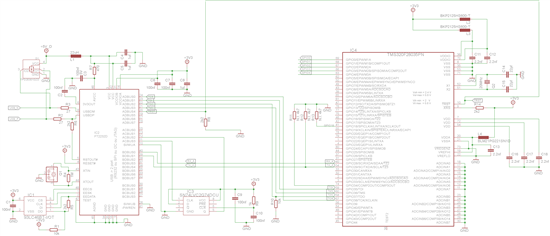
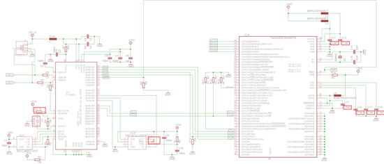
I created the card using the example of F2803xcontrolCARD-SCH[R1] and USBDockingStation_Schematic [R3].

My schematic :

A program for test is hrpwm_duty_sfo_v6 of example ccsv4 ( v121) for DSP2803x.

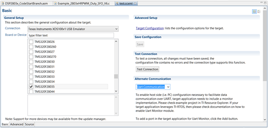
With this config:

I have program eeprom of FTDI ft232 like in wiki : http://processors.wiki.ti.com/index.php/XDS100

I have no idea if you have one ...

  • bob parker said:
    C28xx: GEL Output:
    Device Calibration not complete, check if device is unlocked and recalibrate.

    GEL target initialization is failing because it cannot access the target memory. Can you confirm that the device is indeed unlocked?

  • The device is new and I did not lock the device.

    I tried to unlock the device, no message. But when I relaunch the debug, I now have the following message in addition to the other:

    C28xx: Can't Run Target CPU: (Error -1140 @ 0x0) Lost debug connection to device. Reset the device, and retry the operation. If error persists, confirm configuration, power-cycle the board, and/or try more reliable JTAG settings (e.g. lower TCLK). (Emulation package 5.1.232.0)

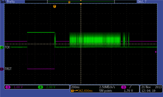
    I watched the TCK and TRST signals (it is well to 1MHz), and I do not see any error :

    In my config of test, the JTAG TCLK frequency is by defaut: fixed default 1.0MHz frequency.


  • Please run the "Test Connection" utility as described below:

    http://processors.wiki.ti.com/index.php/Debugging_JTAG_Connectivity_Problems#Code_Composer_Studio_v5

    Post the results here.

    Thanks

    ki

  • The result :
    [Start]

    Execute the command:

    %ccs_base%/common/uscif/dbgjtag -f %boarddatafile% -rv -o -F inform,logfile=yes -S pathlength -S integrity

    [Result]


    -----[Print the board config pathname(s)]------------------------------------

    C:\Users\parker\AppData\Local\.TI\693494126\
        0\0\BrdDat\testBoard.dat

    -----[Print the reset-command software log-file]-----------------------------

    This utility has selected a 100- or 510-class product.
    This utility will load the adapter 'jioserdesusb.dll'.
    The library build date was 'Aug 20 2013'.
    The library build time was '22:56:19'.
    The library package version is '5.1.232.0'.
    The library component version is '35.34.40.0'.
    The controller does not use a programmable FPGA.
    The controller has a version number of '4' (0x00000004).
    The controller has an insertion length of '0' (0x00000000).
    This utility will attempt to reset the controller.
    This utility has successfully reset the controller.

    -----[Print the reset-command hardware log-file]-----------------------------

    The scan-path will be reset by toggling the JTAG TRST signal.
    The controller is the FTDI FT2232 with USB interface.
    The link from controller to target is direct (without cable).
    The software is configured for FTDI FT2232 features.
    The controller cannot monitor the value on the EMU[0] pin.
    The controller cannot monitor the value on the EMU[1] pin.
    The controller cannot control the timing on output pins.
    The controller cannot control the timing on input pins.
    The scan-path link-delay has been set to exactly '0' (0x0000).

    -----[The log-file for the JTAG TCLK output generated from the PLL]----------

    There is no hardware for programming the JTAG TCLK frequency.

    -----[Measure the source and frequency of the final JTAG TCLKR input]--------

    There is no hardware for measuring the JTAG TCLK frequency.

    -----[Perform the standard path-length test on the JTAG IR and DR]-----------

    This path-length test uses blocks of 512 32-bit words.

    The test for the JTAG IR instruction path-length succeeded.
    The JTAG IR instruction path-length is 38 bits.

    The test for the JTAG DR bypass path-length succeeded.
    The JTAG DR bypass path-length is 1 bits.

    -----[Perform the Integrity scan-test on the JTAG IR]------------------------

    This test will use blocks of 512 32-bit words.
    This test will be applied just once.

    Do a test using 0xFFFFFFFF.
    Scan tests: 1, skipped: 0, failed: 0
    Do a test using 0x00000000.
    Scan tests: 2, skipped: 0, failed: 0
    Do a test using 0xFE03E0E2.
    Scan tests: 3, skipped: 0, failed: 0
    Do a test using 0x01FC1F1D.
    Scan tests: 4, skipped: 0, failed: 0
    Do a test using 0x5533CCAA.
    Scan tests: 5, skipped: 0, failed: 0
    Do a test using 0xAACC3355.
    Scan tests: 6, skipped: 0, failed: 0
    All of the values were scanned correctly.

    The JTAG IR Integrity scan-test has succeeded.

    -----[Perform the Integrity scan-test on the JTAG DR]------------------------

    This test will use blocks of 512 32-bit words.
    This test will be applied just once.

    Do a test using 0xFFFFFFFF.
    Scan tests: 1, skipped: 0, failed: 0
    Do a test using 0x00000000.
    Scan tests: 2, skipped: 0, failed: 0
    Do a test using 0xFE03E0E2.
    Scan tests: 3, skipped: 0, failed: 0
    Do a test using 0x01FC1F1D.
    Scan tests: 4, skipped: 0, failed: 0
    Do a test using 0x5533CCAA.
    Scan tests: 5, skipped: 0, failed: 0
    Do a test using 0xAACC3355.
    Scan tests: 6, skipped: 0, failed: 0
    All of the values were scanned correctly.

    The JTAG DR Integrity scan-test has succeeded.

    [End]
  • You have a good JTAG connection with the device.

    Enable debug server logging and try to connect again. When you get the error again, stop the logging and the zip up the log and attach it here for us to analyze.

    Thanks

    ki

  • Thanks for the log. Unfortunately there was not a lot of information in there to help.

    Could you attach the startup GEL file you are using?

  • My ccxml

    0250.test.xml
    <?xml version="1.0" encoding="UTF-8" standalone="no"?>
    <configurations XML_version="1.2" id="configurations_0">
    
    <configuration XML_version="1.2" id="Texas Instruments XDS100v1 USB Emulator_0">
            <instance XML_version="1.2" desc="Texas Instruments XDS100v1 USB Emulator_0" href="connections/TIXDS100usb_Connection.xml" id="Texas Instruments XDS100v1 USB Emulator_0" xml="TIXDS100usb_Connection.xml" xmlpath="connections"/>
            <connection XML_version="1.2" id="Texas Instruments XDS100v1 USB Emulator_0">
                <instance XML_version="1.2" href="drivers/tixds100c28x.xml" id="drivers" xml="tixds100c28x.xml" xmlpath="drivers"/>
                <instance XML_version="1.2" href="drivers/tixds100cla.xml" id="drivers" xml="tixds100cla.xml" xmlpath="drivers"/>
                <property Type="choicelist" Value="0" id="Emulator Selection"/>
                <platform XML_version="1.2" id="platform_0">
                    <instance XML_version="1.2" desc="TMS320F28035_0" href="devices/f28035.xml" id="TMS320F28035_0" xml="f28035.xml" xmlpath="devices"/>
                <device HW_revision="1" XML_version="1.2" description="" id="TMS320F28035_0" partnum="TMS320F28035">
                        <cpu HW_revision="1.0" XML_version="1.2" description="CPU" id="C28xx_0" isa="TMS320C28XX">
                            <property Type="choicelist" Value="0" id="bypass"/>
                            <property Type="choicelist" Value="0" id="Slave Processor"/>
                        </cpu>
                    </device>
                </platform>
            </connection>
        </configuration>
    </configurations>
    

    My gel (location C:\ti\ccsv5\ccs_base\emulation\gel ) 7028.f28035.gel

  • Hello,

    Sorry if I just disturb the discussion. I just had the same problem, regarding this:

    bob parker said:
    C28xx: Can't Run Target CPU: (Error -1041 @ 0x0) The emulator reported an error. Confirm emulator configuration and connections, reset the emulator, and retry the operation. (Emulation package 5.1.232.0)
    C28xx: Trouble Reading Register PC: (Error -1156 @ 0x0) Device may be operating in low-power mode. Do you want to bring it out of this mode? (Emulation package 5.1.232.0)

    The issue in my case was that I had proper target settings, but used the target configuration for other C2000. I had experimented with the Launchpad Piccolo F28027 and then accidentally used that target configuration for loading the program into Delfino F28335. The target could get connection, but terminated session when tried to load the program for wrong processor.

    Everything got fine, when I turned my attention to the type of configuration I am launching in the moment.(Though both of targets were configured in .ccxml correctly)

    Hope this will help you.

    Best Regards.

  • On my board, the device is TMS320F28035PNS.

    My target configuration in ccxml is TM320F28035.

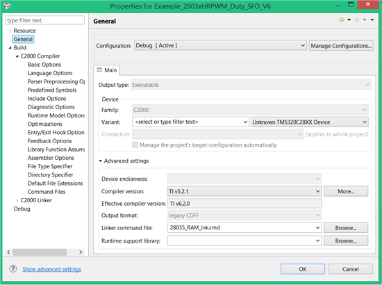
    I look at the properties of my project and i have for device "unknow TMS320C28XX Device".

    I change the device by TMS320F28035, and I have this error:

    !ERROR: The C2000v5.2.1 compiler, or any version compatible with it, is not currently installed! Please migrate the project to one of the supported compilers first.

    I change the compiler version 5.2.1 by 6.2.0, rebuild, relaunch and and I still have the same problem.

  • If you have an idea, I'm interested ;)

  • hmm... i'm running out of ideas...

    can you try starting a project-less debug session and try to connect that way? Also do not use any GEL startup file.

  • Hi Even I am facing the same problem while connecting custom TMS320F2812 board with xds100v1 The xds100v1 connects to the targets board in my earlier version of ccs 4.1.2 but after upgrading to ccs 5.5.0.000777 version its giving the error (Error -1155 @ 0x0)Device may be operating in low-power mode. after connecting once Any idea or suggestion would be of great help Thanks in Advance
  • Sorry for the absence of response I busy.

    I buy the Exprimenter's Kit USB Docking Station and f28035 controlCARD

    I run the program and it works. So I think the problem is the hardware side..

  • I look at my schematic, but I did not see much difference with the schematic of Exprimenter's Kit USB Docking Station and f28035 controlCARD.

    My schematic :


    If someone has an idea, because I'm stuck


  • Schematic with correction :

    1- on FT2232D the resistor on pin RESET# is necessary for pull down internally .

    2 - on SN74LVC2G74 , PRE connected on VCC , I do not know why but it is in the schematic of the kit to experiment's USB Docking Station.

    3 - capacitor on the supply TMS320, the value is 2.2μF to meet the reset time at startup.

  • I've been plagued by this error. I suspected the latch on pins 11, 12, since they seem to be associated with Power_Loss_Detect (from the testBoard.dat file). So I put an LED with 1kR pull-up resistor on the output of the latch (U4 on the Experimenter's kit schematic; see ControlSUITE for the schematic). The LED lights up on power-up, as expected (because the clear input has a capacitor to ground). When I run a connection test from CCS or attempt to use the JTAG emulator, pin 11 gets toggled which sets the latch and turns the LED off.
    To my surprise, the presence of the LED cured the problem (at least so far; it's been quite intermittent). It may be that with all the EMI from the inverters I'm debugging (controlled by a TMS320F28335 controlCARD), the latch clears itself somehow. Ok, now that I write this, I can't see why it would help, but it seems to. I hope that others can benefit from this.

  • Any suggestion about this issue? I have got the same phenomenon that connect debug interface correctly but can not program flash.

    1. Click on test mode shows JTAG scan successfully.

    2. But load program failed.

    Here's the information while clicking on test mode:

    [Start]

    Execute the command:

    %ccs_base%/common/uscif/dbgjtag -f %boarddatafile% -rv -o -F inform,logfile=yes -S pathlength -S integrity

    [Result]


    -----[Print the board config pathname(s)]------------------------------------

    C:\Users\Administrator\AppData\Local\.TI\
    213602635\0\0\BrdDat\testBoard.dat

    -----[Print the reset-command software log-file]-----------------------------

    This utility has selected a 100- or 510-class product.
    This utility will load the adapter 'jioserdesusb.dll'.
    The library build date was 'Apr 2 2012'.
    The library build time was '21:41:04'.
    The library package version is '5.0.681.0'.
    The library component version is '35.34.39.0'.
    The controller does not use a programmable FPGA.
    The controller has a version number of '4' (0x00000004).
    The controller has an insertion length of '0' (0x00000000).
    This utility will attempt to reset the controller.
    This utility has successfully reset the controller.

    -----[Print the reset-command hardware log-file]-----------------------------

    The scan-path will be reset by toggling the JTAG TRST signal.
    The controller is the FTDI FT2232 with USB interface.
    The link from controller to target is direct (without cable).
    The software is configured for FTDI FT2232 features.
    The controller cannot monitor the value on the EMU[0] pin.
    The controller cannot monitor the value on the EMU[1] pin.
    The controller cannot control the timing on output pins.
    The controller cannot control the timing on input pins.
    The scan-path link-delay has been set to exactly '0' (0x0000).

    -----[The log-file for the JTAG TCLK output generated from the PLL]----------

    There is no hardware for programming the JTAG TCLK frequency.

    -----[Measure the source and frequency of the final JTAG TCLKR input]--------

    There is no hardware for measuring the JTAG TCLK frequency.

    -----[Perform the standard path-length test on the JTAG IR and DR]-----------

    This path-length test uses blocks of 512 32-bit words.

    The test for the JTAG IR instruction path-length succeeded.
    The JTAG IR instruction path-length is 38 bits.

    The test for the JTAG DR bypass path-length succeeded.
    The JTAG DR bypass path-length is 1 bits.

    -----[Perform the Integrity scan-test on the JTAG IR]------------------------

    This test will use blocks of 512 32-bit words.
    This test will be applied just once.

    Do a test using 0xFFFFFFFF.
    Scan tests: 1, skipped: 0, failed: 0
    Do a test using 0x00000000.
    Scan tests: 2, skipped: 0, failed: 0
    Do a test using 0xFE03E0E2.
    Scan tests: 3, skipped: 0, failed: 0
    Do a test using 0x01FC1F1D.
    Scan tests: 4, skipped: 0, failed: 0
    Do a test using 0x5533CCAA.
    Test 5 Word 182: scanned out 0x5533CCAA and scanned in 0x2A93CCAA.
    Test 5 Word 183: scanned out 0x5533CCAA and scanned in 0x5699E655.
    Test 5 Word 221: scanned out 0x5533CCAA and scanned in 0x2A99CCAA.
    Test 5 Word 222: scanned out 0x5533CCAA and scanned in 0x5539E655.
    Scan tests: 5, skipped: 0, failed: 1
    Do a test using 0xAACC3355.
    Test 6 Word 217: scanned out 0xAACC3355 and scanned in 0xD5661355.
    Test 6 Word 218: scanned out 0xAACC3355 and scanned in 0xAACE19AA.
    Test 6 Word 268: scanned out 0xAACC3355 and scanned in 0xD4CC3355.
    Test 6 Word 269: scanned out 0xAACC3355 and scanned in 0xD56619AA.
    The details of the first 8 errors have been provided.
    The utility will now report only the count of failed tests.
    Scan tests: 6, skipped: 0, failed: 2
    Some of the values were corrupted - 0.4 percent.

    The JTAG IR Integrity scan-test has failed.

    -----[Perform the Integrity scan-test on the JTAG DR]------------------------

    This test will use blocks of 512 32-bit words.
    This test will be applied just once.

    Do a test using 0xFFFFFFFF.
    Scan tests: 1, skipped: 0, failed: 0
    Do a test using 0x00000000.
    Scan tests: 2, skipped: 0, failed: 0
    Do a test using 0xFE03E0E2.
    Scan tests: 3, skipped: 0, failed: 0
    Do a test using 0x01FC1F1D.
    Scan tests: 4, skipped: 0, failed: 0
    Do a test using 0x5533CCAA.
    Scan tests: 5, skipped: 0, failed: 0
    Do a test using 0xAACC3355.
    Scan tests: 6, skipped: 0, failed: 0
    All of the values were scanned correctly.

    The JTAG DR Integrity scan-test has succeeded.

    [End]

    Regards,

    Jack

  • Hi Jack,

    Jack Tan80 said:
    1. Click on test mode shows JTAG scan successfully.

    Actually, you IR scan failed:

    Jack Tan80 said:

    ----[Perform the Integrity scan-test on the JTAG IR]------------------------

    This test will use blocks of 512 32-bit words.
    This test will be applied just once.

    Do a test using 0xFFFFFFFF.
    Scan tests: 1, skipped: 0, failed: 0
    Do a test using 0x00000000.
    Scan tests: 2, skipped: 0, failed: 0
    Do a test using 0xFE03E0E2.
    Scan tests: 3, skipped: 0, failed: 0
    Do a test using 0x01FC1F1D.
    Scan tests: 4, skipped: 0, failed: 0
    Do a test using 0x5533CCAA.
    Test 5 Word 182: scanned out 0x5533CCAA and scanned in 0x2A93CCAA.
    Test 5 Word 183: scanned out 0x5533CCAA and scanned in 0x5699E655.
    Test 5 Word 221: scanned out 0x5533CCAA and scanned in 0x2A99CCAA.
    Test 5 Word 222: scanned out 0x5533CCAA and scanned in 0x5539E655.
    Scan tests: 5, skipped: 0, failed: 1
    Do a test using 0xAACC3355.
    Test 6 Word 217: scanned out 0xAACC3355 and scanned in 0xD5661355.
    Test 6 Word 218: scanned out 0xAACC3355 and scanned in 0xAACE19AA.
    Test 6 Word 268: scanned out 0xAACC3355 and scanned in 0xD4CC3355.
    Test 6 Word 269: scanned out 0xAACC3355 and scanned in 0xD56619AA.
    The details of the first 8 errors have been provided.
    The utility will now report only the count of failed tests.
    Scan tests: 6, skipped: 0, failed: 2
    Some of the values were corrupted - 0.4 percent.

    The JTAG IR Integrity scan-test has failed.

    This is a low-level failure usually not related to the software (i.e. CCS, drivers, etc) but some HW stability issue. Try some of the general suggestion in the JTAG troubleshooting guide:

    http://software-dl.ti.com/ccs/esd/documents/ccsv7_debugging_jtag_connectivity_issues.html#strategy-for-debugging-jtag-connectivity-problems

    specifically, #3 and #5 are most applicable. Check the integrity of all the HW connections and try lowering TCLK for more stability.

    You are also using an old (unsupported) version of CCS. While your issue is likely not related to CCS, I would recommend updating your CCS version.

    Thanks

    ki

  • Hi Ki,

    Thanks for your suggestion. This device is comes from factory after assembly, and the device has download key and password in it, so it cause this problem.

    After using key load session, this issue has been resolved.

    Thanks anyway.

    Regards,
    Jack