This thread has been locked.

If you have a related question, please click the "Ask a related question" button in the top right corner. The newly created question will be automatically linked to this question.

Failure to Re-Program XDS100v2


Version of the host OS: Windows 10 Pro 64-bit

Exact version of CCS: 6.1.0.00104 

Reference board: AM335x Starter Kit

Current board: Custom version of the AM335x Starter Kit

Debug Probe: XDS100v2 REV 3.0, Part No: BH-USB-100v2, S/N: ND9533

Following the steps outlined here: (processors.wiki.ti.com/.../XDS100) for reprogramming the XDS100v2 EEPROM

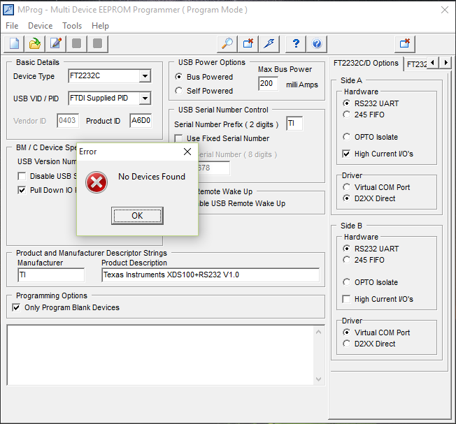
Current Problem: When following the steps to re-program the EEPROM on the XDS100v2, the re-program fails.  This occurs after the initial open of the XDS100_wUART.ept file, the scan and the erase.  If I read the device after the erase the device shows FF for all locations.  When I try to re-program it fails and outputs an error message stating no devices found.  Below are screenshots from the initial scan, the erase, the read to show FF and the failure to re-program.

Open XDS100_wUART.ept file:
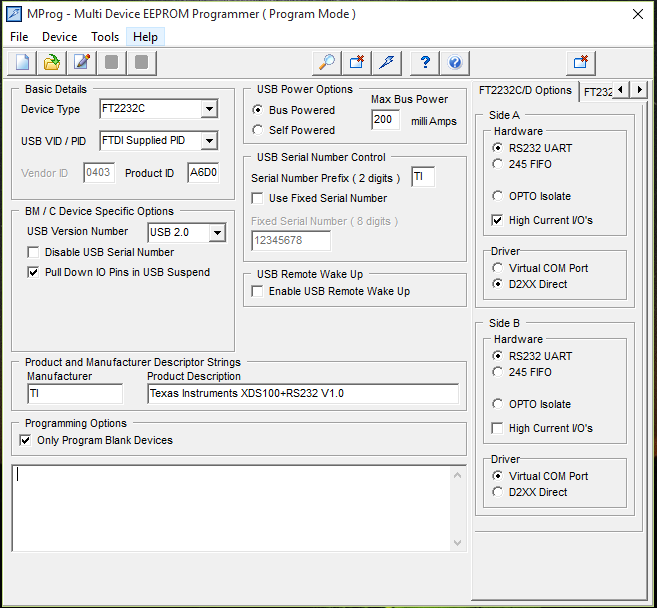
Scan:

Erase:

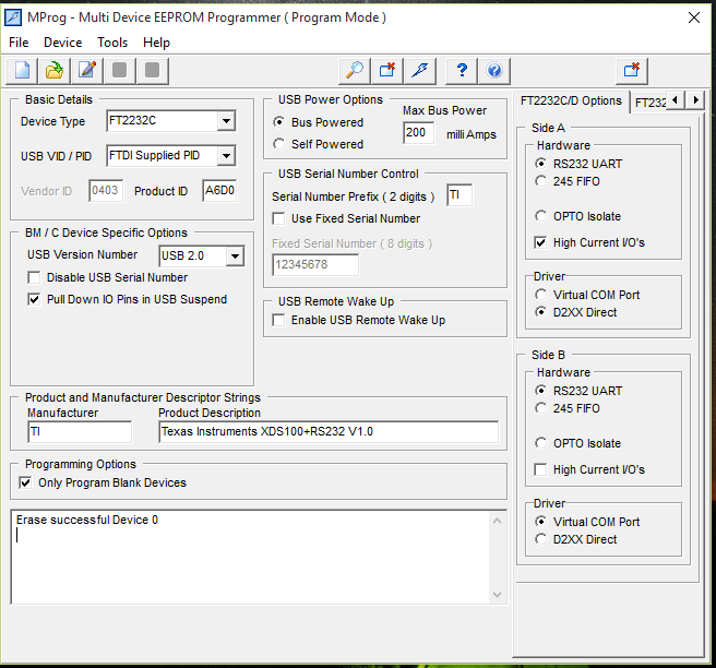
Read of erased device for verification:

Program:

  • Hi,

    The detail that strikes me is the fact you selected a FT2232C, while the XDS100v2 design uses a FT2232H. This alone may be the cause of the programming failure.

    I send attached the template for my BH-USB100v2 debugger, so you could try to bring yours back to life.

    One additional detail is that FTDI is not supporting MProg anymore, but I am not sure if that is causing the trouble (I never had any trouble with either this or FTProg).

    Hope this helps,

    Rafael

    BH_USB100v2.zip

  • Rafael,
    I will try your attached template shortly.
    I just wanted to make a comment that the selected FT2232C was not selected by me. All settings within MProg are not changeable once you load the .ept file. These selections are loaded with the file and I did not change anything from the posted instruction set, simply followed them.
  • Rafael,
    I was able to use your file and successfully reprogram the XDS100v2.
    Thanks for your help and support.
  • Hi,

    Thanks for confirming the file worked.

    Also, thank you for the heads up regarding the .ept file.

    There are two available on the XDS100 page: one provided with the design package and one available in a link at the wiki page (the one with the invalid FT2232C). The one inside the design package uses the correct device (FT2232H) but seems to have different UART and VCP configurations when compared to the one I just sent you.

    My guess is that older versions of CCS (v4, perhaps earlier v5) were compatible with different FTDI settings, thus the variability of templates. I will fix this confusion in the wiki.

    Regards,
    Rafael
  • desouza said:
    There are two available on the XDS100 page:

    Is it because the XDS100v1 used a FT2232C/D device, whereas the XDS100v2 uses a FT2232H?

    [The FT2232H supports USB 2.0 Hi-Speed and the FT2232C/D support USB 2.0 Full-Speed]

  • Chester,

    That would explain the FT2232C (although it should have been D), but even still my standalone XDS100v1 has differences when compared to what is posted. In any case, the mix up of files shouldn't be there.

    Regards,
    Rafael
  • Thanks Rafael,
    The continuing issue that I am having with regards to the XDS100v2 is that I cannot successfully connect to my target device within CCS.
    I am debugging a custom board (built to the AM335x starter kit reference design) and trying to debug using JTAG. I also have a starter kit that I am using as a control to verify memory values within CCS once connected. I am trying to dump the boot analysis file once connected. I have been working with Brad Griffis on this and you can track the conversation (although its a fairly large thread) here:

    e2e.ti.com/.../425059

    We were working on re-programming the FT2232H IC to enable JTAG debugging when I had the issues listed above that we already worked through. Since then, I have been able to get the XDS100v2 re-programmed with your file and was able to connect to the starter kit through CCS (so I know the debugger is alive and well again). I am currently looking for some assistance with getting my custom board's FT2232H correctly configured to work with CCS so I can start debugging with JTAG back in my original thread.

    The error message I get when I try to connect to my target within CCS is as follows:
    CortxA8: Error connecting to the target: (Error -1170 @ 0x0) Unable to access the DAP. Reset the device, and retry the operation. If error persists, confirm configuration, power-cycle the board, and/or try more reliable JTAG settings (e.g. lower TCLK). (Emulation package 6.0.14.0)

    Please let me know if you need any additional information from within CCS. I'm happy to post anything you need.