Hey Guys,
It seems that I am having linker issues.
I have this verified code as seen below:
//
//
//CODE
//
//
#include "DSP28x_Project.h" // Device Headerfile and Examples Include File
#include "f2802x_common/include/clk.h"
#include "f2802x_common/include/flash.h"
#include "f2802x_common/include/gpio.h"
#include "f2802x_common/include/pie.h"
#include "f2802x_common/include/pll.h"
#include "f2802x_common/include/pwr.h"
#include "f2802x_common/include/wdog.h"
#include "f2802x_common/include/adc.h"
#include "f2802x_common/include/sci.h"
#include "f2802x_common/include/i2c.h"
CPU_Handle myCpu;
PLL_Handle myPll;
WDOG_Handle myWDog;
ADC_Handle myAdc;
CLK_Handle myClk;
FLASH_Handle myFlash;
GPIO_Handle myGpio;
PIE_Handle myPie;
PWM_Handle myPwm1;
SCI_Handle mySci;
// Prototype statements for functions found within this file.
interrupt void xint1_isr(void);
interrupt void adc_isr(void);
interrupt void adc_isr_pressure(void);
void Init();
void ADC_INIT_Fn();
void ADC_SETUP_Fn();
void pwm_Init_();
void Motor_stop();
void Motor_forward();
void Motor_reverse();
void set_duty( int a);
//------------------I2C Prototypes START-------------------//
void I2CA_Init(void);
Uint16 Values[6];
Uint16 instr=0x02;
int i;
int data[4] = {1,2,3,4};
int I2C_NUMBYTES = 4;
//-------------------I2C Prototypes END-------------------//
//-------------------UART/SCI Prototypes START-------------------//
interrupt void sciaRxIsr(void);
void scia_init();
void scia_xmit(int a);
void scia_intpt_en();
void send_msg();
void send_back(char data);
unsigned char msg[]="send any data now- Controller will send back it";
unsigned char msg2[]="You Sent:";
unsigned char rx_data;
//-------------------UART/SCI Prototypes END-------------------//
// Global variables for this example
volatile uint32_t Xint1Count;
int32_t adc_button_max= 800;
int32_t adc_button_min = 4095;
int32_t adc_slide_min = 20;
int32_t adc_slide_max = 4085;
//Numbers for Testing Rig///
//int32_t adc_slide_min = 2915;
//int32_t adc_slide_max = 3045;
////////////////////////////
int32_t constant = 0;
int32_t adc_slide_pot = 0;
int32_t adc_button = 0;
int32_t slope = 0;
int32_t delta = 25;
int32_t expected_value = 0;
int32_t top_new = 0;
//PWM
int32_t CMPA=0;
int32_t TBPRD = 4096;
#define DELAY 100000 // us
#define MOTOR_SWITCH_DELAY 10 // us
enum State {STOP = 0, FORWARD, REVERSE};
uint8_t Previous_state = STOP, Current_state = STOP;
int main(void)
{
// Initialize all GPIOs and variables
Init();
//Init I2c
InitSysCtrl(); // Step 1. Initialize System Control: Need this for UART AND I2c to function properly
//InitI2CGpio(); //Shouldnt need this anymore due to intialization in Init()
I2CA_Init(); // Step 4. Initialize all the Device Peripherals
//initialize adc
ADC_INIT_Fn();
ADC_SETUP_Fn();
// Set up chip to good state
Motor_stop();
//UART INIT
scia_intpt_en();
scia_init();
send_msg();
//Perform necessary calculations to linearize motor states
//number multiplied by 1000 to allow for integer calculations
//int32_t top = (adc_slide_max-adc_slide_min);
int32_t bottom = (adc_button_max - adc_button_min);
top_new = ((adc_slide_max-adc_slide_min)<<10);
slope = top_new/bottom;
//slope = (((adc_slide_min-adc_slide_max)<<10)/(adc_button_max - adc_button_min));
constant = adc_slide_max - ((slope * adc_button_max)>>10);
set_duty(2096);
for(;;)
{
//----------------------------------I2C Start-------------------------------------//
// I2C Application loop
int i=0;
for( i =0 ;i < 2; i++ )
{
I2caRegs.I2CSAR = 0x38; //Set slave address
I2caRegs.I2CCNT = I2C_NUMBYTES; //Numbe rof bytes to transfer
I2caRegs.I2CFFTX.all = 0x6000; //enable FIFO mode and reset TX FIFO
I2caRegs.I2CDXR = data[0]; //Send data[0-3]
I2caRegs.I2CDXR = data[1]; //Store in next FIFO level
I2caRegs.I2CDXR = data[2]; //Store in next FIFO level
I2caRegs.I2CDXR = data[3]; //Store in next FIFO level
I2caRegs.I2CMDR.bit.TRX = 1; //Set to Transmit mode
I2caRegs.I2CMDR.bit.MST = 1; //Set to Master mode
I2caRegs.I2CMDR.bit.FREE = 1;//Run in FREE mode
I2caRegs.I2CMDR.bit.STP = 1; // release the bus after Tx
I2caRegs.I2CMDR.bit.STT = 1; //Send the start bit, transmission will follow
while(I2caRegs.I2CSTR.bit.XRDY == 1){}; // --> got stuck here after first run <--
I2caRegs.I2CCNT = 6; //read 6 bytes from sensor
I2caRegs.I2CMDR.bit.TRX = 0; //Set to Recieve mode
I2caRegs.I2CMDR.bit.MST = 1; //Set to Master mode
I2caRegs.I2CMDR.bit.FREE = 1; //Run in FREE mode
I2caRegs.I2CMDR.bit.STP = 1; //Stop when internal counter becomes 0
I2caRegs.I2CMDR.bit.STT = 1; //Repeated start, Reception will follow
for(i = 0; i < 6; i++)
{
while(I2caRegs.I2CSTR.bit.RRDY == 1){}; //I2CDRR not ready to read?
Values[i] = I2caRegs.I2CDRR;
}
} // end of for(;;)
//----------------------------------------------I2C END-----------------------------------------------------------//
//---------------------------------------ADC/CACULATION START---------------------------------//
Previous_state = Current_state;
// This is where you collect data
// Wait for ADC interrupt, must go before state change interrupt
ADC_forceConversion(myAdc, ADC_SocNumber_0);
ADC_forceConversion(myAdc,ADC_SocNumber_1);
adc_slide_pot = ADC_readResult(myAdc, ADC_SocNumber_0);
adc_button = ADC_readResult(myAdc, ADC_SocNumber_1 );
expected_value = ((slope * adc_button)>>10) + constant;
if(abs(expected_value - adc_slide_pot) < delta)
{
Current_state = STOP;
Motor_stop();
DELAY_US(DELAY);
continue;
}
// This is where you determine the next state
// This is also where you adjust the Duty cycle based on the PID results
if (adc_slide_pot < adc_slide_max && adc_slide_pot > adc_slide_min)
{
if (adc_slide_pot < expected_value )
{
Current_state = FORWARD;
}
else if(adc_slide_pot > expected_value)
{
Current_state = REVERSE;
}
else
{
Current_state = STOP;
}
}
else
{
Current_state = STOP;
}
//---------------------------------------ADC/CACULATION END---------------------------------//
// This is where you act on said state change
// Here you process said state change
switch(Current_state)
{
case STOP:
if(Previous_state != STOP)
Motor_stop();
break;
case FORWARD:
if(Previous_state != FORWARD)
Motor_forward();
break;
case REVERSE:
if(Previous_state != REVERSE)
Motor_reverse();
break;
default:
Current_state = STOP;
if(Previous_state != STOP)
Motor_stop();
}
}
}
interrupt void xint1_isr(void)
{
// This needs to set pin low
GPIO_setLow(myGpio, GPIO_Number_12);
// expected_value += 500;
//
// if(expected_value > adc_slide_max)
// expected_value = adc_slide_min;
// Acknowledge this interrupt to get more from group 1
PIE_clearInt(myPie, PIE_GroupNumber_1);
}
interrupt void adc_isr(void)
{
//discard ADCRESULT0 as part of the workaround to the 1st sample errata for rev0
ADC_clearIntFlag(myAdc, ADC_IntNumber_1); // Clear ADCINT1 flag reinitialize for next SOC
PIE_clearInt(myPie, PIE_GroupNumber_10);// Acknowledge interrupt to PIE
return;
}
interrupt void adc_isr_pressure(void)
{
//discard ADCRESULT7 as part of the workaround to the 1st sample errata for rev0
ADC_clearIntFlag(myAdc, ADC_IntNumber_2); // Clear ADCINT1 flag reinitialize for next SOC
PIE_clearInt(myPie, PIE_GroupNumber_10);// Acknowledge interrupt to PIE
return;
}
//---------------------------------------MOTOR STOP START-------------------------------------------//
void Motor_stop()
{
GPIO_setMode(myGpio, GPIO_Number_0, GPIO_0_Mode_GeneralPurpose);
GPIO_setDirection(myGpio, GPIO_Number_0, GPIO_Direction_Input);
GPIO_setMode(myGpio, GPIO_Number_1, GPIO_1_Mode_GeneralPurpose);
GPIO_setDirection(myGpio, GPIO_Number_1, GPIO_Direction_Input);
GPIO_setMode(myGpio, GPIO_Number_2, GPIO_0_Mode_GeneralPurpose);
GPIO_setDirection(myGpio, GPIO_Number_2, GPIO_Direction_Input);
GPIO_setMode(myGpio, GPIO_Number_3, GPIO_1_Mode_GeneralPurpose);
GPIO_setDirection(myGpio, GPIO_Number_3, GPIO_Direction_Input);
}
//---------------------------------------MOTOR STOP END-------------------------------------------//
//---------------------------------------MOTOR FOWARD START-------------------------------------------//
void Motor_forward()
{
Motor_stop();
DELAY_US(MOTOR_SWITCH_DELAY);
//sets top connected GPIO0 to PWM function
GPIO_setMode(myGpio, GPIO_Number_0, GPIO_0_Mode_EPWM1A);
GPIO_setDirection(myGpio, GPIO_Number_0, GPIO_Direction_Output);
//set bottom connected Gpio2 to on position
// GPIO_setMode(myGpio, GPIO_Number_2, GPIO_2_Mode_GeneralPurpose);
// GPIO_setDirection(myGpio,GPIO_Number_2, GPIO_Direction_Output);
// GPIO_setHigh(myGpio, GPIO_Number_2);
}
//---------------------------------------MOTOR FOWARD END-------------------------------------------//
//---------------------------------------MOTOR REVERSE START-------------------------------------------//
void Motor_reverse()
{
Motor_stop();
DELAY_US(MOTOR_SWITCH_DELAY);
//sets top connected GPIO1 to PWM function
GPIO_setMode(myGpio, GPIO_Number_1, GPIO_1_Mode_EPWM1B);
GPIO_setDirection(myGpio, GPIO_Number_1, GPIO_Direction_Output);
//set bottom connected Gpio2 to on position
// GPIO_setMode(myGpio, GPIO_Number_3, GPIO_2_Mode_GeneralPurpose);
// GPIO_setDirection(myGpio,GPIO_Number_3, GPIO_Direction_Output);
// GPIO_setHigh(myGpio, GPIO_Number_3);
}
//---------------------------------------MOTOR REVERSE END-------------------------------------------//
void Init()
{
// Initialize all the handles needed for this application
myClk = CLK_init((void *)CLK_BASE_ADDR, sizeof(CLK_Obj));
myCpu = CPU_init((void *)NULL, sizeof(CPU_Obj));
myFlash = FLASH_init((void *)FLASH_BASE_ADDR, sizeof(FLASH_Obj));
myGpio = GPIO_init((void *)GPIO_BASE_ADDR, sizeof(GPIO_Obj));
myPie = PIE_init((void *)PIE_BASE_ADDR, sizeof(PIE_Obj));
myPll = PLL_init((void *)PLL_BASE_ADDR, sizeof(PLL_Obj));
myWDog = WDOG_init((void *)WDOG_BASE_ADDR, sizeof(WDOG_Obj));
myAdc = ADC_init((void *)ADC_BASE_ADDR, sizeof(ADC_Obj));
myPwm1 = PWM_init((void *)PWM_ePWM1_BASE_ADDR, sizeof(PWM_Obj));
mySci = SCI_init((void *)SCIA_BASE_ADDR, sizeof(SCI_Obj));
// Perform basic system initialization
WDOG_disable(myWDog);
CLK_enableAdcClock(myClk);
(*Device_cal)();
//Select the internal oscillator 1 as the clock source
CLK_setOscSrc(myClk, CLK_OscSrc_Internal);
// Setup the PLL for x10 /2 which will yield 50Mhz = 10Mhz * 10 / 2
PLL_setup(myPll, PLL_Multiplier_10, PLL_DivideSelect_ClkIn_by_2);
//from UART
//PLL_setup(myPll, PLL_Multiplier_12, PLL_DivideSelect_ClkIn_by_2);
// Disable the PIE and all interrupts
PIE_disable(myPie);
PIE_disableAllInts(myPie);
CPU_disableGlobalInts(myCpu);
CPU_clearIntFlags(myCpu);
// // If running from flash copy RAM only functions to RAM
// #ifdef _FLASH
// memcpy(&secureRamFuncs_RunStart, &secureRamFuncs_LoadStart, (Uint32) &secureRamFuncs_LoadSize);
// #endif
#ifdef _FLASH
// Copy time critical code and Flash setup code to RAM
// This includes the following ISR functions: EPwm1_timer_isr(), EPwm2_timer_isr()
// and FLASH_setup();
// The RamfuncsLoadStart, RamfuncsLoadSize, and RamfuncsRunStart
// symbols are created by the linker. Refer to the F2280270.cmd file.
memcpy(&RamfuncsRunStart, &RamfuncsLoadStart, (size_t)&RamfuncsLoadSize);
// Call Flash Initialization to setup flash waitstates
// This function must reside in RAM
FLASH_setup(myFlash);
#endif // end #ifdef _FLASH
// Setup a debug vector table and enable the PIE
PIE_setDebugIntVectorTable(myPie);
PIE_enable(myPie);
// Register interrupt handlers in the PIE vector table
PIE_registerPieIntHandler(myPie, PIE_GroupNumber_1, PIE_SubGroupNumber_4, (intVec_t)&xint1_isr);
// Enable XINT1 and XINT2 in the PIE: Group 1 interrupt 4 & 5
// Enable INT1 which is connected to WAKEINT
PIE_enableInt(myPie, PIE_GroupNumber_1, PIE_InterruptSource_XINT_1);
CPU_enableInt(myCpu, CPU_IntNumber_1);
// Enable Global Interrupts
CPU_enableGlobalInts(myCpu);
//GPIO_setMode(myGpio, GPIO_Number_2, GPIO_2_Mode_GeneralPurpose);
//GPIO_setDirection(myGpio, GPIO_Number_2, GPIO_Direction_Output);
//GPIO_setMode(myGpio, GPIO_Number_3, GPIO_3_Mode_GeneralPurpose);
//GPIO_setDirection(myGpio, GPIO_Number_3, GPIO_Direction_Output);
//Setup GPIO 0&1 for PWM output
GPIO_setMode(myGpio, GPIO_Number_0, GPIO_0_Mode_EPWM1A);
GPIO_setMode(myGpio, GPIO_Number_1, GPIO_1_Mode_EPWM1B);
//Initialize PWM
CLK_disableTbClockSync(myClk);
pwm_Init_();
CLK_enableTbClockSync(myClk);
//INITIALIZE UART GPIO
// Initalize GPIO
GPIO_setPullUp(myGpio, GPIO_Number_19, GPIO_PullUp_Enable);
GPIO_setPullUp(myGpio, GPIO_Number_12, GPIO_PullUp_Disable);
GPIO_setQualification(myGpio, GPIO_Number_19, GPIO_Qual_ASync);
GPIO_setMode(myGpio, GPIO_Number_19, GPIO_19_Mode_SCIRXDA);
GPIO_setMode(myGpio, GPIO_Number_12, GPIO_12_Mode_SCITXDA);
//follow example from UART for I2c Initialization
GPIO_setPullUp(myGpio, GPIO_Number_28, GPIO_PullUp_Enable);
GPIO_setPullUp(myGpio, GPIO_Number_29, GPIO_PullUp_Enable);
GPIO_setMode(myGpio, GPIO_Number_28, GPIO_28_Mode_SDDA);
GPIO_setMode(myGpio, GPIO_Number_29, GPIO_29_Mode_SCLA);
// GPIO12 is XINT1,
GPIO_setExtInt(myGpio, GPIO_Number_12, CPU_ExtIntNumber_1);
// Configure XINT1
PIE_setExtIntPolarity(myPie, CPU_ExtIntNumber_1, PIE_ExtIntPolarity_FallingEdge);
// Enable XINT1
PIE_enableExtInt(myPie, CPU_ExtIntNumber_1);
}
//----------------------------------ADC Functions START-------------------------------------//
void ADC_INIT_Fn()
{
ADC_enableBandGap(myAdc);
ADC_enableRefBuffers(myAdc);
ADC_powerUp(myAdc);
ADC_enable(myAdc);
ADC_setVoltRefSrc(myAdc, ADC_VoltageRefSrc_Int);
}
void ADC_SETUP_Fn()
{
//set up adc for slide pot
PIE_registerPieIntHandler(myPie, PIE_GroupNumber_10, PIE_SubGroupNumber_1, (intVec_t)&adc_isr);
PIE_enableAdcInt(myPie, ADC_IntNumber_3); // Enable ADCINT1 in PIE
//Note: Channel ADCINA1 will be double sampled to workaround the ADC 1st sample issue for rev0 silicon errata
ADC_setIntPulseGenMode(myAdc, ADC_IntPulseGenMode_Prior); //ADCINT1 trips after AdcResults latch
ADC_enableInt(myAdc, ADC_IntNumber_3); //Enabled ADCINT1
ADC_setIntMode(myAdc, ADC_IntNumber_3, ADC_IntMode_ClearFlag); //Disable ADCINT1 Continuous mode
ADC_setIntSrc(myAdc, ADC_IntNumber_3, ADC_IntSrc_EOC0); //setup EOC0 to trigger ADCINT1 to fire
ADC_setSocChanNumber (myAdc, ADC_SocNumber_0, ADC_SocChanNumber_A3); //set SOC0 channel select to ADCINA4
ADC_setSocTrigSrc(myAdc, ADC_SocNumber_0, ADC_SocTrigSrc_EPWM1_ADCSOCA); //set SOC0 start trigger on EPWM1A, due to round-robin SOC0 converts first then SOC1
ADC_setSocSampleWindow(myAdc, ADC_SocNumber_0, ADC_SocSampleWindow_7_cycles); //set SOC0 S/H Window to 7 ADC Clock Cycles, (6 ACQPS plus 1)
//set up adc for presssure pot
PIE_registerPieIntHandler(myPie, PIE_GroupNumber_10, PIE_SubGroupNumber_1, (intVec_t)&adc_isr_pressure);
PIE_enableAdcInt(myPie, ADC_IntNumber_7); // Enable ADCINT7 in PIE
//Note: Channel ADCINA1 will be double sampled to workaround the ADC 1st sample issue for rev0 silicon errata
ADC_setIntPulseGenMode(myAdc, ADC_IntPulseGenMode_Prior); //ADCINT1 trips after AdcResults latch
ADC_enableInt(myAdc, ADC_IntNumber_7); //Enabled ADCINT1
ADC_setIntMode(myAdc, ADC_IntNumber_7, ADC_IntMode_ClearFlag); //Disable ADCINT1 Continuous mode
ADC_setIntSrc(myAdc, ADC_IntNumber_7, ADC_IntSrc_EOC1); //setup EOC7 to trigger ADCINT7 to fire
ADC_setSocChanNumber (myAdc, ADC_SocNumber_1, ADC_SocChanNumber_A7); //set SOC07 channel select to ADCINA3
ADC_setSocTrigSrc(myAdc, ADC_SocNumber_1, ADC_SocTrigSrc_EPWM1_ADCSOCA); //set SOC2 start trigger on EPWM1A, due to round-robin SOC0 converts first then SOC1
ADC_setSocSampleWindow(myAdc, ADC_SocNumber_1, ADC_SocSampleWindow_7_cycles); //set SOC0 S/H Window to 7 ADC Clock Cycles, (6 ACQPS plus 1)
}
//----------------------------------ADC Functions END-------------------------------------//
//----------------------------------PWM Functions START-------------------------------------//
void pwm_Init_()
{
CLK_enablePwmClock(myClk, PWM_Number_1);
// Setup TBCLK
PWM_setPeriod(myPwm1, TBPRD); // Set timer period 801 TBCLKs
PWM_setPhase(myPwm1, 0x0000); // Phase is 0
PWM_setCount(myPwm1, 0x0000); // Clear counter
// Setup counter mode
PWM_setCounterMode(myPwm1, PWM_CounterMode_UpDown); // Count up and down
PWM_disableCounterLoad(myPwm1); // Disable phase loading
PWM_setHighSpeedClkDiv(myPwm1, PWM_HspClkDiv_by_10); // Clock ratio to SYSCLKOUT
PWM_setClkDiv(myPwm1, PWM_ClkDiv_by_1);
///setup for GPIO6 PWM
// Setup shadowing
PWM_setShadowMode_CmpA(myPwm1, PWM_ShadowMode_Shadow);
PWM_setLoadMode_CmpA(myPwm1, PWM_LoadMode_Zero);
// Set actions
PWM_setActionQual_CntUp_CmpA_PwmA(myPwm1, PWM_ActionQual_Clear); // Set PWM1A on event A, up count
PWM_setActionQual_CntDown_CmpA_PwmA(myPwm1, PWM_ActionQual_Set); // Clear PWM1A on event A, down count
//SETUP for GPIO 7 PWM
// Setup shadowing
PWM_setShadowMode_CmpB(myPwm1, PWM_ShadowMode_Shadow);
PWM_setLoadMode_CmpB(myPwm1, PWM_LoadMode_Zero);
// Set actions
PWM_setActionQual_CntUp_CmpB_PwmB(myPwm1, PWM_ActionQual_Clear); // Set PWM1A on event A, up count
PWM_setActionQual_CntDown_CmpB_PwmB(myPwm1, PWM_ActionQual_Set); // Clear PWM1A on event A, down count
}
void set_duty( int a)
{
CMPA = a;
PWM_setCmpA(myPwm1, CMPA);
PWM_setCmpB(myPwm1, CMPA);// Set compare A value
}
//----------------------------------PWM Functions END-------------------------------------//
//----------------------------------I2C Functions START-------------------------------------//
void I2CA_Init(void)
{
I2caRegs.I2CSAR = 0x38; // Slave address - EEPROM control code
I2caRegs.I2CPSC.all = 6; // Prescaler - need 7-12 Mhz on module clk for 60MHz CPU
I2caRegs.I2CCLKL = 4200; // NOTE: must be non zero - set to 1kHz
I2caRegs.I2CCLKH = 4200; // NOTE: must be non zero - set to 1kHz
I2caRegs.I2CIER.all = 0x3E; // Enable SCD,XRDY,RRDY,ARDY,NACK interrupts
I2caRegs.I2CMDR.bit.IRS = 1; // Take I2C out of reset, Stop I2C when suspended
I2caRegs.I2CFFTX.all = 0x0000; // Enable FIFO mode and TXFIFO
I2caRegs.I2CFFRX.all = 0x0000; // Enable RXFIFO, clear RXFFINT,
return;
}
//----------------------------------I2C Functions END-------------------------------------//
//----------------------------------UART/SCI Functions START-------------------------------------//
interrupt void sciaRxIsr(void)
{
rx_data = SCI_getData(mySci);
send_back(rx_data);
PIE_clearInt(myPie, PIE_GroupNumber_9);
}
void scia_init()
{
CLK_enableSciaClock(myClk);
SCI_disableParity(mySci);
SCI_setNumStopBits(mySci, SCI_NumStopBits_One);
SCI_setCharLength(mySci, SCI_CharLength_8_Bits);
SCI_enableRx(mySci);
SCI_enableTx(mySci);
SCI_enableRxInt(mySci);
SCI_setBaudRate(mySci, SCI_BaudRate_9_6_kBaud);
SCI_enable(mySci);
}
void scia_intpt_en()
{
PIE_enable(myPie);
PIE_registerPieIntHandler(myPie, PIE_GroupNumber_9, PIE_SubGroupNumber_1, (intVec_t)&sciaRxIsr);
PIE_enableInt(myPie, PIE_GroupNumber_9, PIE_InterruptSource_SCIARX);
CPU_enableInt(myCpu, CPU_IntNumber_9);
CPU_enableGlobalInts(myCpu); // Enable Global Interrupts
}
void scia_xmit(int a)
{
while(SCI_getTxFifoStatus(mySci) != SCI_FifoStatus_Empty); //while (SciaRegs.SCIFFTX.bit.TXFFST != 0) {}
SCI_putDataBlocking(mySci, a); // SciaRegs.SCITXBUF=a;
}
void send_msg()
{
int i=0;
while(msg[i]!='\0')
{
scia_xmit(msg[i]);
i++;
}
}
void send_back(char data)
{
int i=0;
while(msg2[i]!='\0')
{
scia_xmit(msg2[i]);
i++;
}
scia_xmit(rx_data);
scia_xmit('\r');
scia_xmit('\n');
}
//----------------------------------UART/SCI Functions END-------------------------------------//
//===========================================================================
// No more.
//===========================================================================
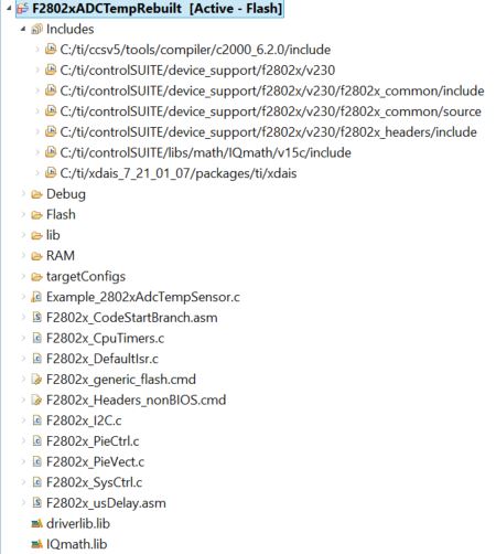
Now whenever I try to compile it i get the following errors as seen here in the log file:
-l"C:/Users/Carlo/Documents/GIT_Controlled_Projects/falcon/CCS_WKspace/Example_F2802xAdcTempSensor/../../f2802x_common/cmd/F2802x_generic_flash.cmd" -l"rts2800_ml.lib" -l"IQmath.lib"
error: cannot find file
"C:/Users/Carlo/Documents/GIT_Controlled_Projects/falcon/CCS_WKspace/Example
_F2802xAdcTempSensor/../../f2802x_common/cmd/F2802x_generic_flash.cmd"
warning: creating output section ".cinit" without a SECTIONS specification
warning: creating output section ".ebss" without a SECTIONS specification
warning: creating output section ".econst" without a SECTIONS specification
warning: creating output section ".reset" without a SECTIONS specification
warning: creating output section ".text" without a SECTIONS specification
warning: creating output section "codestart" without a SECTIONS specification
warning: creating output section "ramfuncs" without a SECTIONS specification
error: no valid memory range(NULL) available for placement of ".text"
error: program will not fit into available memory. placement with
alignment/blocking fails for section ".text" size 0xcce page 0
error: program will not fit into available memory. placement with
alignment/blocking fails for section ".econst" size 0x200 page 0. Available
memory ranges:
error: program will not fit into available memory. placement with
alignment/blocking fails for section ".cinit" size 0xae page 0. Available
memory ranges:
error: program will not fit into available memory. run placement with
alignment/blocking fails for section ".ebss" size 0x9b page 1. Available
memory ranges:
DEV_EMU size: 0x105 unused: 0x1 max hole: 0x1
SYS_PWR_CTL size: 0x3 unused: 0x0 max hole: 0x0
FLASH_REGS size: 0x60 unused: 0x58 max hole: 0x58
CSM size: 0x10 unused: 0x0 max hole: 0x0
ADC_RESULT size: 0x20 unused: 0x0 max hole: 0x0
CPU_TIMER0 size: 0x8 unused: 0x0 max hole: 0x0
CPU_TIMER1 size: 0x8 unused: 0x0 max hole: 0x0
CPU_TIMER2 size: 0x8 unused: 0x0 max hole: 0x0
PIE_CTRL size: 0x20 unused: 0x6 max hole: 0x6
PIE_VECT size: 0x100 unused: 0x0 max hole: 0x0
COMP1 size: 0x20 unused: 0xf max hole: 0xf
COMP2 size: 0x20 unused: 0xf max hole: 0xf
EPWM1 size: 0x40 unused: 0x0 max hole: 0x0
EPWM2 size: 0x40 unused: 0x0 max hole: 0x0
EPWM3 size: 0x40 unused: 0x0 max hole: 0x0
EPWM4 size: 0x40 unused: 0x0 max hole: 0x0
ECAP1 size: 0x20 unused: 0x0 max hole: 0x0
GPIOCTRL size: 0x40 unused: 0x0 max hole: 0x0
GPIODAT size: 0x20 unused: 0x0 max hole: 0x0
GPIOINT size: 0x20 unused: 0x16 max hole: 0x16
SYSTEM size: 0x20 unused: 0x1 max hole: 0x1
SPIA size: 0x10 unused: 0x0 max hole: 0x0
SCIA size: 0x10 unused: 0x0 max hole: 0x0
NMIINTRUPT size: 0x10 unused: 0x0 max hole: 0x0
XINTRUPT size: 0x10 unused: 0x0 max hole: 0x0
ADC size: 0x80 unused: 0x2f max hole: 0x2f
I2CA size: 0x40 unused: 0x1e max hole: 0x1e
PARTID size: 0x1 unused: 0x0 max hole: 0x0
CSM_PWL size: 0x8 unused: 0x0 max hole: 0x0
error: program will not fit into available memory. placement with
alignment/blocking fails for section "ramfuncs" size 0x5a page 0. Available
memory ranges:
error: program will not fit into available memory. placement with
alignment/blocking fails for section ".reset" size 0x2 page 0. Available
memory ranges:
error: program will not fit into available memory. placement with
alignment/blocking fails for section "codestart" size 0x2 page 0. Available
memory ranges:
undefined first referenced
symbol in file
--------- ----------------
_RamfuncsLoadSize ./Example_2802xAdcTempSensor.obj
_RamfuncsLoadStart ./Example_2802xAdcTempSensor.obj
_RamfuncsRunStart ./Example_2802xAdcTempSensor.obj
error: unresolved symbols remain
error: errors encountered during linking; "Example_F2802xAdcTempSensor.out" not
built
>> Compilation failure
gmake: *** [Example_F2802xAdcTempSensor.out] Error 1
gmake: Target `all' not remade because of errors.
**** Build Finished ****
I am using a C2000 TMS320F28027 chip so I know that the code above is not maxing out the memory, thus the problem has to be in the linker.
Here is my current CCS General setup is as seen below:
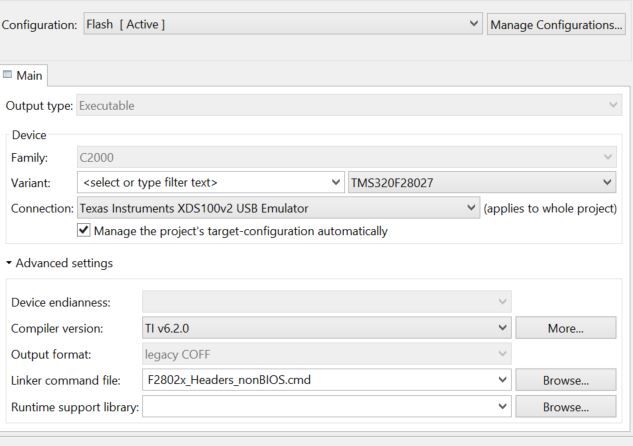
I have tried everything to fix this problem, however so far no progress.
Any and all help is appreciated.
Thank you in advance,
Carlo