This thread has been locked.

If you have a related question, please click the "Ask a related question" button in the top right corner. The newly created question will be automatically linked to this question.

GUI Composer - Serial Communication Packet Format for UART protocol Communication (FTDI Interface) between EVM GUI and MSP430


Hi,

I am using the Serial communication version of GUI Composer, not the JTAG version. 

My setup is as follows:

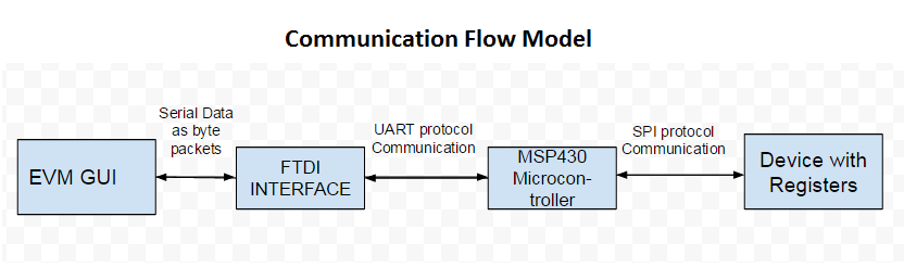
My primary purpose is to understand the Serial data being transferred between the GUI composer and FTDI interface which communicates it using UART protocol to MSP430. I found some information about the same under "Monitor Protocol Documentation" in the following link:

http://processors.wiki.ti.com/index.php/ProgramModelUart_GuiComposer

Is there any other resource that I could refer to understand the packet format related details?

I have the following questions:

  1. What data is contained in the MAU part of the header packet?
  2. I found the following details from the link above:
    • Byte 1
      • bit 1 = always 1
      • bit 2 = 1(R) or 0(w)
      • bits 3-8 = 63 bit MAU
    • Bytes 2-5 : 4 byte (32 bit) address. Below is a screenshot of the firmware map file of MSP430 microcontroller with 4 byte addresses for all register variables.

  • Does the 4 bytes (2-5) refer to these register variable addresses or does it refer to a 2 byte register address followed by 2 bytes of data?
  • If so, in case of a read operation, should the 2 bytes of data be skipped?

3. What is the byte packet format of the data? I was able to find bit wise packet format only for the header.

4. What is the byte packet format for the data that is read back from MSP430 microcontroller?

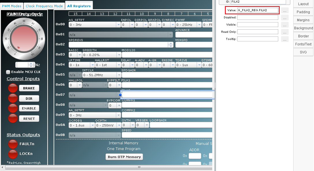
5.How does the change made to a field specific variable by binding (shown in the image below) in the GUI composer reflected in the corresponding register variable (MAP file - shown above) used in the Read/Write operation? Can you give me a pointer on where I could find the relevant information regarding the same?

Any help is greatly appreciated!

Thanks and Regards,

Madhumitha

  • 1. It is the length for read/write action which is used to determine the size of data to be read/written. If you have more than 63 MUAs to read/write then data needs to be broken into multiple transactions. 

    2. It is just the address. We use the same protocol for 16 and 32 bit targets. 

    3. It is in the format of the target. 

    4. Same as above, it follows the format of the target. 

    5. I am not sure I understand your question, thus please clarify if I am answering the wrong question. The symbol entered in GC designer, is converted from a name to an address. The symbolic information also contains data type which gives us the length to read. The address should correspond to what you see in the map file, but length is not part of the .map file. This information is obtained from the program file (i..e .out). This symbol resolution takes place on the host (i.e. your PC) inside of GC Runtime. GC Runtime then creates the read request and sends the address/length to read the data. 

    In the same page that you referred to in your original post, there is a download link for examples of MSP target code, which includes the target side of protocol implementation, which could be helpful in clarifying the target implementation further. 

    Martin

  • Hi!

    In the reply it is mentioned that the data format for reading and writing the data depends on the Target device.

    • The UART protocol is used to communicate with the MSP430, in that case the UART Communication with the BSL (MSP430) has a Data Packet format shown below:

    • Which of the above 2 packet formats ( BSL / UART program model) should be considered?

      Thanks and Regards,

      Madhumitha