This thread has been locked.

If you have a related question, please click the "Ask a related question" button in the top right corner. The newly created question will be automatically linked to this question.

Retrieving load addresses of sections from image file only

Other Parts Discussed in Thread: TMS320C5

Hi all,

I have a firmware image designed to run on a TMS320C5 microprocessor. I have no other files for it, i.e. linking/dsphex command files to identify easily how it was build/linked/imaged. Despite this lack of info, I'm assuming that some of the information, such as the load address of the sections, offsets, length etc... are stored somewhere prior to the section/objects so the processor know where/how to load them at run-time. Using IDA pro, I'm seeking where in the generated image file to look for this information for each section in the firmware. This is do I can properly align the various segments so I can link the functions together (CALLs and branches, along with variables in the CINIT section). Below is what I found so far:

The current file I have is a firmware which appears to contain multiple objects, including functions from the RTS50.lib (boot.asm, f_add.asm etc...). I can see the different sections (.text1, .cinit1, .const1, .text2, .cinit2, etc...). I took a look at the first few words of the firmware and saw the follow 4 words:

8000 0000 0000 F001 <c_int0>

And based on this, I assumed the first .text section within the firmware started at 0x8000 and it actually seems to work (the c_int0 and subsequent function aligns). However I can't really understand if I was just lucky and how to understand how the other following sections are loaded. For example, following the CINIT/CONST segments of other objects, I can see similar looking words right before the .text section:

8095 5000 0000 F001
...
8000 03F0 0000 F009
...
800A 0000 0000 F089

However when I look at the addresses calls/branching instructions within the .text section following these words, some are in lower addresses which don't appear to work out. For example I can see:

CALL #3CEHh
...
BCND #68A3h
...

So I'm currently confused as to how I can determine how/where code sections are loaded program memory using only the firmware image. If anyone can help me, I would be grateful, as I already spend the last 3 days trying to figure it out. The help file in CC doesn't seem to have the details I need. I understand the ROMS/dsphex -image concept, but not the reverse process. Of course there is no symbol information to easily locate this information. 

Thanks

J.

  • I don't know what format your "firmware image" is, so I can't tell you anything about it, and I really can't do much without knowing the format. Are you sure you're not looking at a COFF executable object file? I'd be pretty surprised to see section names in an "image" file. There really isn't a reverse process with image files as input; the point of an image file is to strip out the metadata, so it's gone. I'd have to study up on the C5x architecture to begin to help you with those opcodes, but consider that they might be absolute addresses or PC-relative offsets.
  • The firmware image is the output of the dsphex (or hex2000) compiler tool. When I wrote that I see the ".text" or ".cinit" sections, what I really meant was that by searching the compiled functions/sections within the firmware, I can see those sections. For example, by compiling the c_int0 bootstrap function, and then searching for the same words (i.e. E388 <cur+1> 7A89 <var_init> 7A89 <main> 7A89 <C$$EXIT>)  within the firmware, I can conclude that this is the .text section. Same as for the CINIT, by search for <len> <addr> <bytes>, such as 0001 8000 00AD 0001 8001 0FFF ... 0000 0000 I can conclude this is the CINIT section.  There are no strings such as ".cinit" or ".text" within the file, so it's not a COFF file with symbolic information, it's a COFF file stripped of these symbols for imaging purpose.

  • Okay, I'm familiar with the hex utility output. What you should be seeing is a set of line-oriented records. Depending on the format, the load address is either embedded in each line, or in a separate record. Could you post an example of one line from the file so that I can determine the specific format?
  • It may have been used with the -image option in combination with the ROMS property, since the contents are not hex strings, so the output is actually code words for the instructions, for example the first line of the file is

    8000 0000 0000 F001 8002 7DFD BE41 BC00 AE60 0600 ...

    So basically, it's a direct translation from the assembly (based on IDA pro):

    .word 8000
    .word 0000
    .word 0000
    .word F001 (bcndd 8002?)
    c_int0: sar ar0, 0FF82h bd 0BE41h, *br0+, ar5 ldp 0 splk #600h, 60h ...

    I'm not sure what the first 4 words are. I assumed the first one was the load address, but doesn't seem to work for the other sections in the firmware. To summarize, I have a binary image which contains the firmware code for an old medical appliance that runs on the TMS320C5, and I'm trying to disassemble the code.  I'm certain it has been compiled with the Code Composer IDE and the RTS50 library, but not sure how it was linked/imaged.

    Apologies for my poor explanation. I'll do my best to explain it if unclear.

    J.

  • Using -image makes the hex utility fill in gaps between sections so that the output looks like one long, continuous section, but doesn't change the output format. For instance, when I use hex2000, I get Tektronix format by default:
    %4E63C800000000833E000000000000000000000000000000000000000000000000000000000000
    The fields are not space-separated, so you have to know where to break it. The first line says:
    This line holds data that is 0x4E bytes long, is block type 6 (data), has checksum 0x3c, is loaded at address 0x00000000, and that data is 0x833e followed by all zeros.
    hex2000 can produce with spaces between data bytes with either "ASCII-hex" format or "TI-TXT" format, but neither looks quite like you've shown. Are you absolutely sure dsphex generated this file? Are you showing us the exact line as it appears in the image file?

  • Hmm, I guess I misunderstood what the dsphex tool was doing, because this is really a binary file, not a text file with long strings of digits. It's really made to be written to memory directly. Here's a snapshot taken from IDA. I can't post the entire file due to disclosure agreements. But the screenshot shows the first few words of the file. For example at 0x2A you can see E388 8024 7A89 8031 7A89 8047, so

    BCND 802A
    CALL 8031
    CALL 8047

     .

  • I didn't think dsphex had the ability to emit binary image files; this was a feature added recently, and not to old tools like dsphex. Curious...

    Usually binary image files are a verbatim snapshot of the memory; no interpretation is performed. This image is meant to be loaded to a specific address, which is not specified in the file. In this scenario, the initial 0x8000 probably doesn't mean anything to the loader. The trick then is to figure out what the correct starting address is, and everything else should just fall into place.

    I doubt that F001 is meant to be treated as code, because it decodes as BCNDD #8002, !Carry, !BIO, which is a pretty weird instruction, especially for startup code. The first several words before 8002 are probably just a data table. 8002 as "SAR ar0, 0FF82h" is plausible, but BE41 as "bd 0BE41h, *br0+, ar5" is weird because br0+ is bit-reversed addressing, normally only used with algorithms like FFT. I'd guess that it, too, is part of data. Are you sure that c_int0 points into this part of code? How do you know the address of c_int0?

  • Frankly, I don't think there's any code in that block. There are just too many things that don't make sense as instructions.
  • Ok, consider this. Below is the C code of the c_int0 function as defined in the library (RTS50.lib) provided with CC:

    _c_int0:
    	LRLK    AR0,__stack		; set up frame pointer
    	LRLK    AR1,__stack		; set up stack pointer
    	ROVM				; turn off overflow mode
    	SPM     0			; product shift count of zero
    	.if	.tms32050
    	LDPK	0			; access memory mapped regs
    	APL	#0fff9h,PMST		; set NDX = 0 and TRM = 0
    	.endif
    	SSXM				; set SXM=1 for LALK cinit
    	.if	ZERO_WAIT_STATES & .tms32050
    	LDPK	0
    	SPLK	#0,PDWSR
    	.endif
    	LALK    cinit			; get pointer to init tables
    	ADDK    1
    	BZ      skip			; if (cinit == -1)
    	CALL    _var_init,AR1		; var_init() 
    skip:
    	.if	CONST_COPY
    	CALL	const_copy
    	.endif
    	CALL    _main,AR1
    	CALL    _abort,AR1		; to never return...
    _var_init:
    	.if	.tms32025 | .tms3202xx
            ADRK    2			; allocate two words of local memory
            LALK    cinit			; load accumulator with base of table
    	LARP    AR0
    loop:
    	TBLR    *+			; read length 
    	ADDK    1
    	TBLR    *			; read address
    	LAR     AR2,*-			; load variable address into ar2
    	LAR     AR3,*,AR3		; load count into ar3
    	BANZ    copy,*-,AR2		; check for end of t

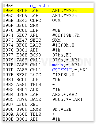
    Now, once compiled using CC and the included debugger, we get the following machine code:

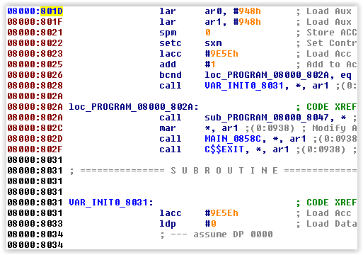
    Now, here's a screenshot of part of the firmware. The c_int0 function prbably starts at 0x801D, with both BF08 ???? BF09 ???? being the two LAR instructions of the c_int0 function, and the 7A89 being the CALL instructions.

    Here's a disassembled view of it (labels added by me)

    It may have some slight differences, but I'm persuaded the code at 0x801D to be a c_int0 function. It totally possible that the words prior to 0x801D are not part of it. I have no clue about their purpose.

  • While the stuff at 0x801d does look like code, and it does start with "lar ar0, #948" "lar ar1, #948", notice that the next instruction should be "CLRC OVM", but is "SPM 0". I think you've found a similar function, but not _c_int0.

    [Edit: Hmm... is this program actually compiled with the _c_int0 from the RTS, or is it a custom boot routine? ]

  • Let's assume for a moment that the code you've identified is in fact a custom _c_int0. I've been assuming that this is a flat binary image with an unknown starting point. This suggest that if you've correctly identified the starting point of _c_int0, which seems plausible (from the very tiny amount of code you've shown in VAR_INIT0_0831), then you'd just need to align the code to 0x8000 and you're all set. However, in an earlier post, you said "However when I look at the addresses calls/branching instructions within the .text section following these words, some are in lower addresses which don't appear to work out." Perhaps this means that the image file is not a flat binary image, but one with address encoded, as you initially suggested. I'm not familiar with any such format, so you'd have to guess based on patterns, as you have also suggested. I don't see anything obvious in the proposed header fragments you've shown; I would probably need to see more of the file to reverse-engineer it.