This thread has been locked.

If you have a related question, please click the "Ask a related question" button in the top right corner. The newly created question will be automatically linked to this question.

ICEPICK?


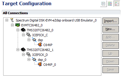
Short question: what is ICEPICK?

Additional, slightly longer questions: what's meant with subpath? What is a router? What is a port number? How come for my TCI6482 DSK board the port number has to be 16, ...not, for instance, 42?

Thanks, Jerry

  • Jerry,

    ICEPick is a dynamic JTAG scan path router.  A subpath is one of the branches of the scan chain that comes out of that router.  The port number set in the CCS target configuration has to match what it is on the device.  You cannot assign any number you want, it is something that is set in the device.


    There is more information here:

    http://processors.wiki.ti.com/index.php/ICEPICK


    Regards,

    John


  • Thank you John,

    is there a way to figure out the "burnt-in" port number of a device?

    In general, I'm interested in what happens after I hit the "Debug Active Project" button. That is, how does my executable get uploaded and placed on the target board via the JTAG interface? For instance I have the following target configuration:

    What "magic" is it that lets me interact with both TMS320 DSPs? I can upload different programs to the different DSPs, and I can inspect the different memory maps of each chip. I couldn't find any TI document yet that explains (in a detailed manner) how emulation works, especially with respect to JTAG and ICEPICK.

    Jerry


  • Jerry,

    For most devices we have a board or device file pre-created.  So that when you create a target configuration like you have in the capture the ICEPick values are all set.  If you click on the "dsp" in the screen capture it will show you the scan path port address of the device.  

    In the configuration you have you are using the onboard emulator, i.e. a JTAG emulator that is built onto the EVM.  That will receive the commands from the debugger to read and write to the device.

    I can look to see if we have any general JTAG information around.

    John

  • This JTAG TI wiki page is too general. "JTAG lets data be moved on- and off-chip non-intrusively, without interrupting the executing device." - that's what I figured out myself. For example I'd like to know how my ".out" file gets through the embedded JTAG board into my DSP's L2 SRAM.

    That is: how is the embedded JTAG able to write into L2 SRAM? How is the embedded JTAG able to read out registers? etc.


    Cheers,

    Jerry

  • Jerry,

    I'm not sure how specific of an explanation you are looking for.  This should give you a general idea of how JTAG works.  I can't supply you with enough detail that you'll be able to go out and build your own emulator, but you should get a picture of how the data flows in and out. 

    Each device has some type of emulation logic that accepts instructions, such as read data, read register, etc.  Each of these pieces of logic has some number of bits that they use for these instructions and for passing data.  You're using a TCI6482.  In this device (and all 64x+ devices) we have a unit that is called IceMaker that does the emulation accesses.  It essentially has a way to access register and data values, etc.  The IceMaker logic has a 38 bit instruction set.  An instruction is given to it by shifting in the  38-bits of an instruction (via TDI) and then telling it to "Execute" (via TMS).  So, IceMaker executes the instruction, and then puts the returned value in a register that will then be shifted out (via TDO).  As we shift the data out, we are also shifting the next instruction in.  You can think of the JTAG scan chain as one big *** register.  When we shift one bit into TDI, we get one bit out of TDO.

    Think about a case where we have 3 64x+ cores in the same chain (numbered 0, 1, 2).  If we want to shift an instruction into core 2, we actually have to shift in 3 x 38 = 114 bits.  We *** in the 38 instruction bits (which will initially be in the register for core 0), then we shift in 76 zeros (also called bypass instructions) in order to get that instruction in the right place.  Then, we have to shift out another 114 bits to get the results out.  So, you can see that for a case where there are many cores, there are many more bits that need to be shifted in and out to get the instruction to go to the right place.

    This is where IcePick becomes handy.  Icepick is also located in the scan chain, and can be configured by scanning in instructions to it.  So, if we have 3 devices connected to icepick, and we want to address CPU 2, we will initially scan a few bits through the chain to configure it so that only CPU 2 is in the chain.  Then we can address CPU 2 with nearly as few bits as we would if it were completely stand alone.(I think there are 4 bits needed as IcePick remains in the chain.  This really saves time if there are many instructions needed to be scanned to one of the devices on the scan chain, as we only need to configure IcePick at the beginning, then we can so many scans to read/write data for a much smaller bit cost than we would if we had to scan through all 3 devices.

    I hope that this makes things more clear.

    Regards,

    Dan


  • Hi Dan,

    thank you very much for your good explanation! It already made the concept behind IcePick clearer to me. I guess IceMaker's instruction set includes instructions which allow to write data to and read data from the DSP's different memory locations. I also guess that after a write instruction is shifted in, the to-be-written data will afterwards be shifted in via TDI. And when a read instruction is shifted in, the requested data will be shifted out via TDO within the next couple of TCK cycles.

    Is there a SPRU or SPRA explaining the IceMaker/IcePick/JTAG architecture and instruction set?

    Thanks,

    Jerry

  • There is a wiki topic for ICEPICK with some additional information that may be helpful:

    http://processors.wiki.ti.com/index.php/ICEPICK

    Thanks

    ki

  • Yep, thanks for the link. I already commented that this wiki page is unfortunately too general for a user to understand how ICEPICK works behind the curtains.

  • Jerry,

    We don't have any documents that detail the instruction sets of the IcePick/IceMaker peripherals.  For 3rd parties that want to implement their own emulators, we supply a Emulation Porting Kit that contains libraries that are used to generate the set of instructions that are scanned by the emulator.  The implementation is not as simple as the overview that I gave you, as there is a lot of activity that goes on behind the scenes. 

    Regards,

    Dan