This thread has been locked.

If you have a related question, please click the "Ask a related question" button in the top right corner. The newly created question will be automatically linked to this question.

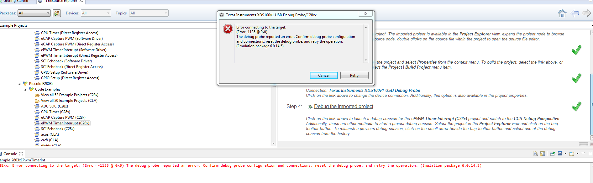
C2000(Piccolo Control Card)Error connecting to the target: (Error -1135 @ 0x0)

Other Parts Discussed in Thread: DRV8412, CONTROLSUITE

I am using a DRV8412 C2 Kit Motor board, and a Controlcard that has a C2000 (F28035) Piccolo MCU. I am having problems with connecting to target.

Error Below : 

Error connecting to the target:
(Error -1135 @ 0x0)
The debug probe reported an error. Confirm debug probe configuration and connections, reset the debug probe, and retry the operation.
(Emulation package 6.0.14.5)

Console Error:

C28xx: Error connecting to the target: (Error -1135 @ 0x0) The debug probe reported an error. Confirm debug probe configuration and connections, reset the debug probe, and retry the operation. (Emulation package 6.0.14.5)

When I go to Test connection. the .ccxml file error pasted below:

[Start: Texas Instruments XDS100v1 USB Debug Probe_0]

Execute the command:

%ccs_base%/common/uscif/dbgjtag -f %boarddatafile% -rv -o -F inform,logfile=yes -S pathlength -S integrity

[Result]


-----[Print the board config pathname(s)]------------------------------------

C:\Users\Tupac\AppData\Local\TEXASI~1\CCS\
ti\2\0\BrdDat\testBoard.dat

-----[Print the reset-command software log-file]-----------------------------

This utility has selected a 100- or 510-class product.
This utility will load the adapter 'jioserdesusb.dll'.
The library build date was 'Sep 4 2015'.
The library build time was '21:59:23'.
The library package version is '6.0.14.5'.
The library component version is '35.35.0.0'.
The controller does not use a programmable FPGA.
The controller has a version number of '4' (0x00000004).
The controller has an insertion length of '0' (0x00000000).
This utility will attempt to reset the controller.
This utility has successfully reset the controller.

-----[Print the reset-command hardware log-file]-----------------------------

The scan-path will be reset by toggling the JTAG TRST signal.
The controller is the FTDI FT2232 with USB interface.
The link from controller to target is direct (without cable).
The software is configured for FTDI FT2232 features.
The controller cannot monitor the value on the EMU[0] pin.
The controller cannot monitor the value on the EMU[1] pin.
The controller cannot control the timing on output pins.
The controller cannot control the timing on input pins.
The scan-path link-delay has been set to exactly '0' (0x0000).

-----[The log-file for the JTAG TCLK output generated from the PLL]----------

There is no hardware for programming the JTAG TCLK frequency.

-----[Measure the source and frequency of the final JTAG TCLKR input]--------

There is no hardware for measuring the JTAG TCLK frequency.

-----[Perform the standard path-length test on the JTAG IR and DR]-----------

This path-length test uses blocks of 64 32-bit words.

The test for the JTAG IR instruction path-length failed.
The JTAG IR instruction scan-path is stuck-at-ones.

The test for the JTAG DR bypass path-length failed.
The JTAG DR bypass scan-path is stuck-at-ones.

-----[Perform the Integrity scan-test on the JTAG IR]------------------------

This test will use blocks of 64 32-bit words.
This test will be applied just once.

Do a test using 0xFFFFFFFF.
Scan tests: 1, skipped: 0, failed: 0
Do a test using 0x00000000.
Test 2 Word 0: scanned out 0x00000000 and scanned in 0xFFFFFFFF.
Test 2 Word 1: scanned out 0x00000000 and scanned in 0xFFFFFFFF.
Test 2 Word 2: scanned out 0x00000000 and scanned in 0xFFFFFFFF.
Test 2 Word 3: scanned out 0x00000000 and scanned in 0xFFFFFFFF.
Test 2 Word 4: scanned out 0x00000000 and scanned in 0xFFFFFFFF.
Test 2 Word 5: scanned out 0x00000000 and scanned in 0xFFFFFFFF.
Test 2 Word 6: scanned out 0x00000000 and scanned in 0xFFFFFFFF.
Test 2 Word 7: scanned out 0x00000000 and scanned in 0xFFFFFFFF.
The details of the first 8 errors have been provided.
The utility will now report only the count of failed tests.
Scan tests: 2, skipped: 0, failed: 1
Do a test using 0xFE03E0E2.
Scan tests: 3, skipped: 0, failed: 2
Do a test using 0x01FC1F1D.
Scan tests: 4, skipped: 0, failed: 3
Do a test using 0x5533CCAA.
Scan tests: 5, skipped: 0, failed: 4
Do a test using 0xAACC3355.
Scan tests: 6, skipped: 0, failed: 5
Some of the values were corrupted - 83.3 percent.

The JTAG IR Integrity scan-test has failed.

-----[Perform the Integrity scan-test on the JTAG DR]------------------------

This test will use blocks of 64 32-bit words.
This test will be applied just once.

Do a test using 0xFFFFFFFF.
Scan tests: 1, skipped: 0, failed: 0
Do a test using 0x00000000.
Test 2 Word 0: scanned out 0x00000000 and scanned in 0xFFFFFFFF.
Test 2 Word 1: scanned out 0x00000000 and scanned in 0xFFFFFFFF.
Test 2 Word 2: scanned out 0x00000000 and scanned in 0xFFFFFFFF.
Test 2 Word 3: scanned out 0x00000000 and scanned in 0xFFFFFFFF.
Test 2 Word 4: scanned out 0x00000000 and scanned in 0xFFFFFFFF.
Test 2 Word 5: scanned out 0x00000000 and scanned in 0xFFFFFFFF.
Test 2 Word 6: scanned out 0x00000000 and scanned in 0xFFFFFFFF.
Test 2 Word 7: scanned out 0x00000000 and scanned in 0xFFFFFFFF.
The details of the first 8 errors have been provided.
The utility will now report only the count of failed tests.
Scan tests: 2, skipped: 0, failed: 1
Do a test using 0xFE03E0E2.
Scan tests: 3, skipped: 0, failed: 2
Do a test using 0x01FC1F1D.
Scan tests: 4, skipped: 0, failed: 3
Do a test using 0x5533CCAA.
Scan tests: 5, skipped: 0, failed: 4
Do a test using 0xAACC3355.
Scan tests: 6, skipped: 0, failed: 5
Some of the values were corrupted - 83.3 percent.

The JTAG DR Integrity scan-test has failed.

[End: Texas Instruments XDS100v1 USB Debug Probe_0]

--------------

I don't know how to fix this. I tried both V1 USB and V2, without connecting to the target, I can't run any code for Motor Control.

  • Is it possible to Factory reset the MCU, Maybe the MCU setting was changed and thats causing the linking error.

  • Hi,

    The issue reported by the Test Connection is explained in the post below:
    e2e.ti.com/.../1629574

    Based on your development kit definitely the connection you need to configure is a XDS100v1. You also need to be sure that all jumpers are properly set and the board is powered correctly. For details check the "How to Run Guide" of your board. If you have controlSUITE installed, this guide is located under C:\ti\controlSUITE\development_kits\DRV8412-C2-KIT_v131\~Docs

    The reason is that the controlCARD that comes with this kit uses a galvanically isolated XDS100 JTAG debugger, which does not automatically provide power to the DSP just by connecting the USB cable (which is expected).

    Hope this helps,
    Rafael
  • Thank you for the reply.

    I was able to fix it by changing switch 3 on the MCU downwards since I was using CCS. The problem I am currently having is my code currently brings a fault in the DRV8412 board "the fault red LED turns on"

    Here is  my code below. It says it compiles right, and in watch window I Can see the full step sequence working properly, just a fault in the board that won't let the motor run.

    //###########################################################################
    #include "DSP28x_Project.h" // Device Headerfile and Examples Include File

    //###########################################################################
    // Global variables used in the project before main code. Declare other // variables in this section of the code.
    //###########################################################################

    #define EPWM_TIMER_TBPRD 2999
    #define EPWM_TIMER_TBSTEP 300

    int16 sector = 0;
    int n = 0;
    int step = 1;

    //###########################################################################
    // Declare the service routines and functions
    //###########################################################################

    /*
    void InitEPwm1Example(void);
    void InitEPwm2Example(void);
    void InitEPwm7Example(void);
    */

    void clockwise(int,float);
    void counter_clockwise(int,float);
    void motor_stop(float);

    void main()
    {

    InitSysCtrl();
    DINT;
    InitPieCtrl();
    IER = 0x0000;
    IFR = 0x0000;
    InitPieVectTable();

    EALLOW;
    SysCtrlRegs.PCLKCR0.bit.TBCLKSYNC = 0;

    GpioCtrlRegs.GPAMUX1.bit.GPIO13 = 00; //muliplex for LEDs
    GpioCtrlRegs.GPAMUX1.bit.GPIO14 = 00;
    GpioCtrlRegs.GPAMUX1.bit.GPIO15 = 00;
    GpioCtrlRegs.GPAMUX2.bit.GPIO16 = 00;
    GpioCtrlRegs.GPAMUX2.bit.GPIO31 = 00;
    GpioCtrlRegs.GPBMUX1.bit.GPIO34 = 00;
    GpioCtrlRegs.GPADIR.bit.GPIO13 = 1; //set as outputs
    GpioCtrlRegs.GPADIR.bit.GPIO14 = 1;
    GpioCtrlRegs.GPADIR.bit.GPIO15 = 1;
    GpioCtrlRegs.GPADIR.bit.GPIO16 = 1;
    GpioCtrlRegs.GPADIR.bit.GPIO31 = 1;
    GpioCtrlRegs.GPBDIR.bit.GPIO34 = 1;

    EDIS;
    /*
    InitEPwm1Example();
    InitEPwm2Example();
    InitEPwm7Example();
    */
    EALLOW;
    SysCtrlRegs.PCLKCR0.bit.TBCLKSYNC = 1; // Enable PWM clock to have the 2 PWM signal synchronized
    EDIS;


    for(;;)
    {
    clockwise(10,600000); //10 cycles for 600ms
    motor_stop(4000000); //stop for 4 sec
    counter_clockwise(10,600000); //10 cycles for 600ms
    motor_stop(5000000); //stop for 5sec
    }

    } //End Main()

    void clockwise(int cycles, float delay) {
    int j = cycles*4;
    int i;
    GpioDataRegs.GPASET.bit.GPIO31=1; //turn on LED 31
    for(i=0;i<j;i++) {
    if (step == 1) { //+Vdc for A and B
    GpioDataRegs.GPASET.bit.GPIO13=1;
    GpioDataRegs.GPASET.bit.GPIO14=1;
    GpioDataRegs.GPACLEAR.bit.GPIO15=1;
    GpioDataRegs.GPACLEAR.bit.GPIO16=1;
    DELAY_US(delay);
    step++; }
    else if (step == 2) {//-Vdc for A, +Vdc for B
    GpioDataRegs.GPACLEAR.bit.GPIO13=1;
    GpioDataRegs.GPASET.bit.GPIO14=1;
    GpioDataRegs.GPASET.bit.GPIO15=1;
    GpioDataRegs.GPACLEAR.bit.GPIO16=1;
    DELAY_US(delay);
    step++; }
    else if (step == 3) {//-Vdc for A and B
    GpioDataRegs.GPACLEAR.bit.GPIO13=1;
    GpioDataRegs.GPACLEAR.bit.GPIO14=1;
    GpioDataRegs.GPASET.bit.GPIO15=1;
    GpioDataRegs.GPASET.bit.GPIO16=1;
    DELAY_US(delay);
    step++; }
    else if (step == 4) {//-Vdc for B, +Vdc for A
    GpioDataRegs.GPASET.bit.GPIO13=1;
    GpioDataRegs.GPACLEAR.bit.GPIO14=1;
    GpioDataRegs.GPACLEAR.bit.GPIO15=1;
    GpioDataRegs.GPASET.bit.GPIO16=1;
    DELAY_US(delay);
    step = 1; }
    else {step = 1;}
    }
    GpioDataRegs.GPACLEAR.bit.GPIO31=1; //turn off LED 31
    }

    void counter_clockwise(int cycles, float delay) {
    int j = cycles*4;
    int i;
    GpioDataRegs.GPBSET.bit.GPIO34=1; //turn on LED 34
    for(i=0;i<j;i++) {
    if (step == 4) {//-Vdc for B, +Vdc for A
    GpioDataRegs.GPASET.bit.GPIO13=1;
    GpioDataRegs.GPACLEAR.bit.GPIO14=1;
    GpioDataRegs.GPACLEAR.bit.GPIO15=1;
    GpioDataRegs.GPASET.bit.GPIO16=1;
    DELAY_US(delay);
    step--; }
    else if (step == 3) {//-Vdc for A and B
    GpioDataRegs.GPACLEAR.bit.GPIO13=1;
    GpioDataRegs.GPACLEAR.bit.GPIO14=1;
    GpioDataRegs.GPASET.bit.GPIO15=1;
    GpioDataRegs.GPASET.bit.GPIO16=1;
    DELAY_US(delay);
    step--; }
    else if (step == 2) {//-Vdc for A, +Vdc for B
    GpioDataRegs.GPACLEAR.bit.GPIO13=1;
    GpioDataRegs.GPASET.bit.GPIO14=1;
    GpioDataRegs.GPASET.bit.GPIO15=1;
    GpioDataRegs.GPACLEAR.bit.GPIO16=1;
    DELAY_US(delay);
    step--; }
    else if (step == 1) {//+Vdc for A and B
    GpioDataRegs.GPASET.bit.GPIO13=1;
    GpioDataRegs.GPASET.bit.GPIO14=1;
    GpioDataRegs.GPACLEAR.bit.GPIO15=1;
    GpioDataRegs.GPACLEAR.bit.GPIO16=1;
    DELAY_US(delay);
    step = 4; }
    else {step = 4;}
    }
    GpioDataRegs.GPBCLEAR.bit.GPIO34=1; //turn off LED 34
    }

    void motor_stop(float delay) {
    DELAY_US(delay);
    }