Tool/software: Code Composer Studio
Hello,
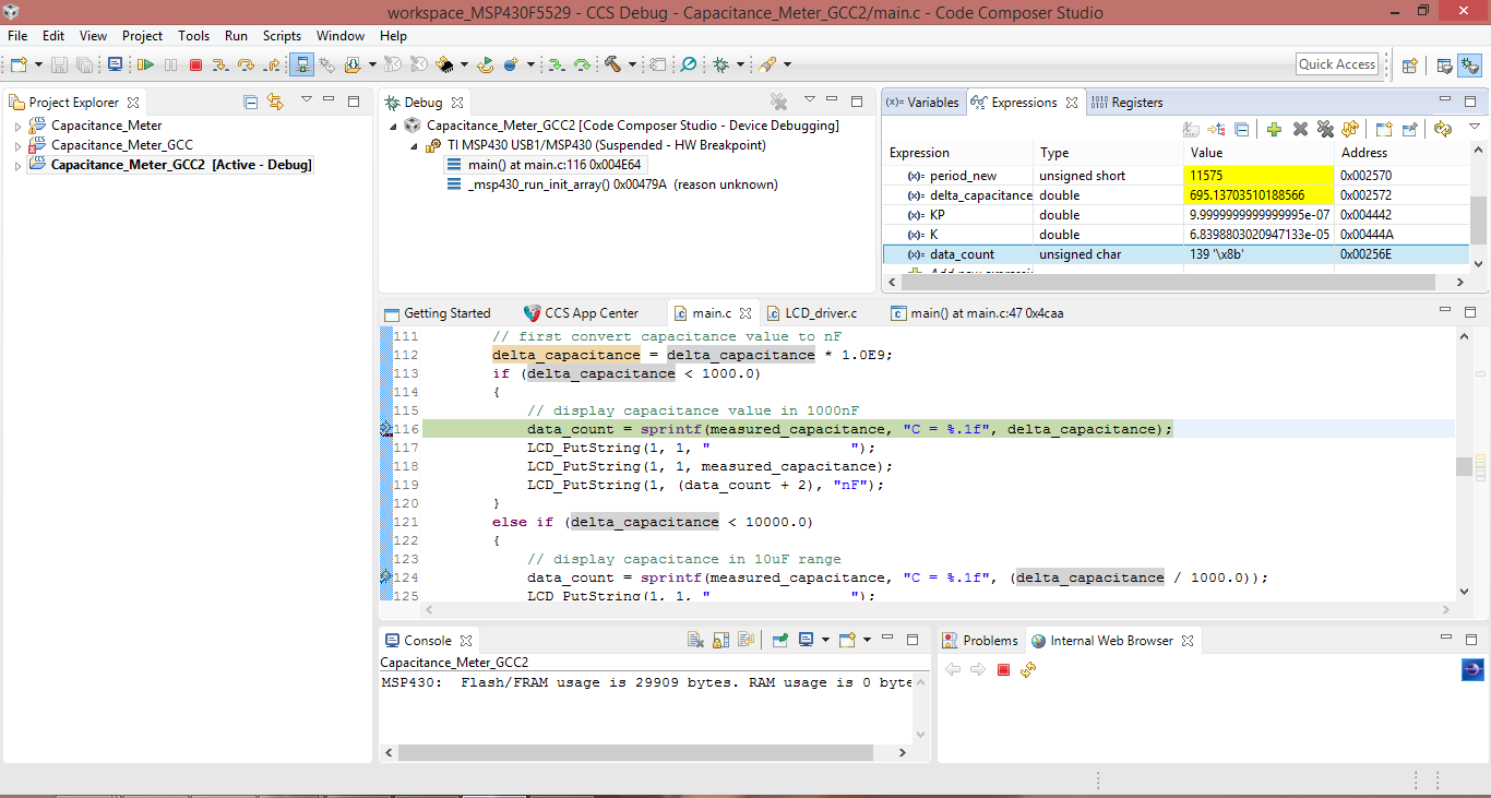
Please I am using CCS v7 with GNU v6.2.1.16. I am using sprintf in my code and it doesn't produce the desired output to the LCD.
The simulator shows the value I am supposed to display but there is nothing on the display. Please I need help in order to resolve this issue.
Please this is the code I am running for reference:
/**
 * Section: Included Files
 */

#include <stdio.h>
#include <stdint.h>
#include "driverlib.h"
#include "LCD_driver.h"

/**
 * Section: Macro Declarations
 */

#define RA  993         // measured value of RA in ohms
#define RB  10030       // measured value of RB in ohms

/**
 * Section: Global Variables Definitions
 */

uint16_t captured_value;
uint16_t previous_capture;
uint16_t period_raw;
uint16_t period_old;
uint16_t period_new;
double delta_period;
double delta_capacitance;								// change in capacitance or measured capacitance
const double K = 1.44 / ((RA) + (2 * (RB)));			// constant for determining capacitance
const double KP = 1.0E-6;								// the value of one timer tick in seconds

/**
 * Section: Function Prototypes
 */

void capture_config(void);
void capture_isr(void);

/**
 * Section: Main Application
 */

int main(void)
{
	// Stop watchdog timer
    WDT_A_hold(WDT_A_BASE);
    GPIO_setAsOutputPin(GPIO_PORT_P1, GPIO_PIN0);

    // set P5.2 as XT2IN
    GPIO_setAsPeripheralModuleFunctionInputPin(GPIO_PORT_P5, GPIO_PIN2 + GPIO_PIN4);
    // set P5.3 as XT2OUT
    GPIO_setAsPeripheralModuleFunctionOutputPin(GPIO_PORT_P5, GPIO_PIN3 + GPIO_PIN5);
    // set frequencies of XT1 and XT2 in Hz
    UCS_setExternalClockSource(32768, 4000000);
    // initialize crystals
    UCS_turnOnXT2(UCS_XT2_DRIVE_4MHZ_8MHZ);
    UCS_turnOnLFXT1(UCS_XT1_DRIVE_0, UCS_XCAP_3);
    // use the crystals to set the clocks
    // initialize master clock with a frequency of 4MHz
    UCS_initClockSignal(UCS_MCLK, UCS_XT2CLK_SELECT, UCS_CLOCK_DIVIDER_1);
    // initialize sub master clock with a frequency of 1MHz
    UCS_initClockSignal(UCS_SMCLK, UCS_XT2CLK_SELECT, UCS_CLOCK_DIVIDER_4);
    // initialize auxilliary clock with a frequency of 32.768KHz
    UCS_initClockSignal(UCS_ACLK, UCS_XT1CLK_SELECT, UCS_CLOCK_DIVIDER_1);

    // configure GPIO for LCD
    P2DIR |= BIT2 + BIT3;
    P3DIR |= BIT7;
    P7DIR |= BIT4;
    P8DIR |= BIT1 + BIT2;

    // initialize LCD
    LCD_Init();
    LCD_PutCmd(_LCD_CLEAR);
    LCD_PutCmd(_LCD_CURSOR_OFF);
    LCD_PutString(1, 1, "Measuring Period");
    LCD_PutString(2, 1, "-Default Value-");
    delay_ms(5000);
    LCD_PutCmd(_LCD_CLEAR);

    // configure timerA for capture mode
    capture_config();

    // allow 555 timer to stabilize?
    delay_ms(5000);

    // measure old period
    period_old = period_raw;

    // array for storing capacitance value as a string
    char measured_capacitance[16];

    // number of characters to output
    uint8_t data_count;

	while (1)
	{
		// measure new period
		period_new = period_raw;

		// calculate change in period
		delta_period = ((float) (period_new - period_old)) * KP;

		// calculate change in capacitance
		delta_capacitance = K * delta_period;

        // format capacitance value
        // first convert capacitance value to nF
        delta_capacitance = delta_capacitance * 1.0E9;
        if (delta_capacitance < 1000.0)
        {
            // display capacitance value in 1000nF
            data_count = sprintf(measured_capacitance, "C = %.1f", delta_capacitance);
            LCD_PutString(1, 1, "                ");
            LCD_PutString(1, 1, measured_capacitance);
            LCD_PutString(1, 10, "nF");
        }
        else if (delta_capacitance < 10000.0)
        {
            // display capacitance in 10uF range
            data_count = sprintf(measured_capacitance, "C = %.1f", (delta_capacitance / 1000.0));
            LCD_PutString(1, 1, "                ");
            LCD_PutString(1, 1, measured_capacitance);
            LCD_PutString(1, 10, "uF");
        }
        else if (delta_capacitance < 100000.0)
        {
            // display capacitance in 100uF range
        }

        // 1 second delay
        delay_ms(1000);

	}
}

/**
 * Section: Function Definitions
 */

void capture_config(void)
{
	// set P1.2 as input
	GPIO_setAsInputPin(GPIO_PORT_P1, GPIO_PIN2);
	// set P1.2 as capture input
	GPIO_setAsPeripheralModuleFunctionInputPin(GPIO_PORT_P1, GPIO_PIN2);

	// initialize timerA for continuous mode operation
	Timer_A_initContinuousModeParam continuous_param = {0};
	continuous_param.clockSource = TIMER_A_CLOCKSOURCE_SMCLK;
	continuous_param.clockSourceDivider = TIMER_A_CLOCKSOURCE_DIVIDER_1;
	continuous_param.timerInterruptEnable_TAIE = TIMER_A_TAIE_INTERRUPT_DISABLE;
	continuous_param.timerClear = TIMER_A_DO_CLEAR;
	continuous_param.startTimer = false;
	Timer_A_initContinuousMode(TIMER_A0_BASE, &continuous_param);

	// initialize timerA capture mode
	Timer_A_clearCaptureCompareInterrupt(TIMER_A0_BASE, TIMER_A_CAPTURECOMPARE_REGISTER_0);
	Timer_A_initCaptureModeParam capture_param = {0};
	capture_param.captureRegister = TIMER_A_CAPTURECOMPARE_REGISTER_1;
	capture_param.captureInterruptEnable = TIMER_A_CAPTURECOMPARE_INTERRUPT_ENABLE;
	capture_param.captureMode = TIMER_A_CAPTUREMODE_RISING_EDGE;
	capture_param.captureInputSelect = TIMER_A_CAPTURE_INPUTSELECT_CCIxA;
	capture_param.synchronizeCaptureSource = TIMER_A_CAPTURE_SYNCHRONOUS;
	capture_param.captureOutputMode = TIMER_A_OUTPUTMODE_OUTBITVALUE;
	Timer_A_initCaptureMode(TIMER_A0_BASE, &capture_param);

	Timer_A_startCounter(TIMER_A0_BASE, TIMER_A_CONTINUOUS_MODE);

	// enable interrupts
	__bis_SR_register(GIE);
}

void capture_isr(void)
{
	static uint8_t interrupt_number = 0;
	interrupt_number++;
	// get captured value
	//captured_value = Timer_A_getCaptureCompareCount(TIMER_A0_BASE, TIMER_A_CAPTURECOMPARE_REGISTER_1);
	captured_value = TA0CCR1;
	if (interrupt_number == 1)
	{
		previous_capture = captured_value;
		//GPIO_setOutputHighOnPin(GPIO_PORT_P1, GPIO_PIN0);
	}
	if (interrupt_number == 2)
	{
		period_raw = captured_value - previous_capture;
		interrupt_number = 0;
		//GPIO_setOutputLowOnPin(GPIO_PORT_P1, GPIO_PIN0);
	}
	// enable interrupts
	__bis_SR_register(GIE);
}

/**
 * Section: Interrupt Service Routine
 */

__attribute__((interrupt(TIMER0_A1_VECTOR)))void TIMER_A0_ISR(void)
{
	switch (__even_in_range(TA0IV, 14))
	{
		case 0:							// none
			break;
		case 2:							// CCR1 IFG
			capture_isr();
			break;
		case 4:							// CCR2 IFG
			break;
		case 6:							// CCR3 IFG
			break;
		case 8:							// CCR4 IFG
			break;
		case 10:						// CCR5 IFG
			break;
		case 12: 						// CCR6 IFG
			break;
		case 14:						// TAOIFG
			break;
		default: 						// never executed
			break;
	}
}
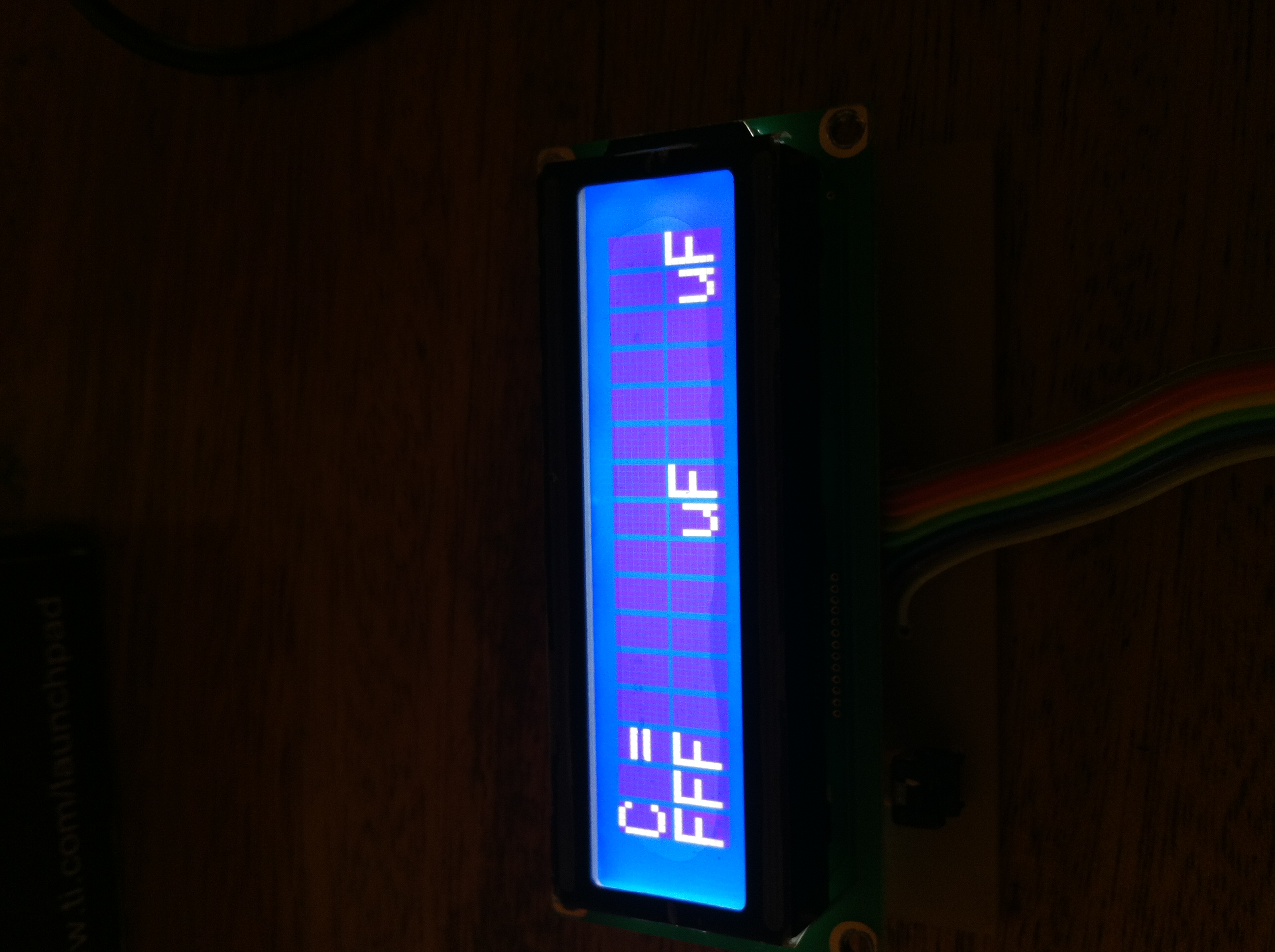
Previously I had this code in the system
data_count = sprintf(measured_capacitance, "C = %.1f", (delta_capacitance / 1000.0));
LCD_PutString(1, 1, " ");
LCD_PutString(1, 1, measured_capacitance);
LCD_PutString(1, (data_count + 2), "uF");
and this is the output that I got on the LCD after a few minutes of operation: